Salisbury Rear Axle Anti-Clonk Cure
All MGB GTs and those MGB roadsters built from 1966/7 were fitted with the Salisbury rear axle. An easy way of verifying what is fitted to your car (as axles are sometimes changed) is to look at the rear of the axle. If there is a cover that is bolted on then it is a Salisbury axle if there are no bolts at the rear but a series of nuts at the front of the differential then the axle is the earlier Banjo type.
After many thousands of miles wear in the diff is inevitable. This can manifest itself as a clonk being both felt and heard on power take up or when slowing down. If your MGB has wire wheels, first check that the hubs and splines are not worn causing this ‘clonk’. If your splines and hubs are sound but the clonk persists or the car is fitted with steel wheels then it is worth checking the universal joints of the propshaft. If the propshaft is sound then the noise may be due to wear in the thrust washers of the planet gears which are housed in the differential. Replacement, if care is taken, is quite straightforward and the parts required are cheap and will help prolong the life of the rear axle before a reconditioned unit is required.
Preparation
As with the majority of work under the car first remove the battery earth lead, to prevent accidental starting, then secure the rear of the car on axle stands. Remove the two rear road wheels. A container can be placed under the drain plug of the axle and the square drive drain plug removed. It is well worth purchasing the correct tool for this job as it makes life so much easier. Allow the oil to drain into the container and replace the drain plug securely.
|
 |
 |
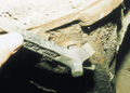
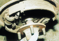
In order to proceed with the replacement of the thrust washer it is necessary to remove only one of the half-shafts by about six inches. Therefore choose one side, then, using a pair of pliers remove the split pin of the main hub nut and use a 15/16th UNF socket to remove the nut. You will need an assistant to put their foot on the brake pedal to hold the shaft in place. Now free off the brake shoe adjuster by about three quarters of a turn and remove the two screws that help hold the drum in place when the road wheel is not fitted. The drum can now be wriggled off. Gently tap the hub and pull it off of the half-shaft. The coned spacer can also be slid off from the shaft.
Back plate removal
 |
 |
 |
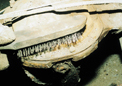
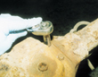
While it is possible to carry out the next procedure without disconnecting the braking circuit it is not advisable to do so. This is mainly due to the high chance of damaging the brake line which obviously has very high safety implications. Therefore, first disconnect the handbrake cable from the lever. Now remove the brake master cylinder top and place some cling film over the opening and replace the cap. It is now possible to remove the rear brake line from the rear wheel cylinder with minimum loss of fluid. Finally, the four bolts that hold the back plate and end cap of the axle in place can be loosened and removed. Now lift the back plate away from the end of the axle.
Release of half shaft
 |
 |
 |
Gaining access and replacing the thrust washers
 |
 |
 |
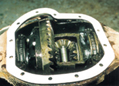 |
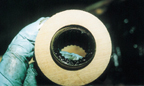
Use a wire brush to thoroughly clean up the area around the rear diff cover. Make sure you clean both the bolt face and surrounding area of the axle casing to ensure that no dirt falls into the differential. Once the area is clean release all of the securing bolts making a mental note to where the handbrake pivot point is attached and the location of the top clips for securing the brake lines. The rear cover can now be gently pulled away.
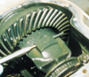
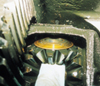
You are now able to see the workings of the differential. Look at the crown wheel (the large cog on the left) and look for any wear lines, cracks or chips. If there is any visible damage you will need to consider replacing the rear axle as a complete unit. The first task is to turn the nose of the differential until the planet gear carrier turns around to reveal the roll pin that holds the main shaft in place for the top and bottom planet gears and to drift the roll pin out. Now that the roll pin is out, once again turn the nose of the differential until the other end of the main pin is facing you. You can now start to drift the main pin out of the carrier, see photos 6 & 7. Take care here not to push the pin too far through as it is very easy to lock the pin against the casing of the axle with no way of pulling it back. You must take great care to avoid this happening as it could render your axle useless. Now observe when the pin has started to move and as soon as it does, turn the nose of the differential around again so that the end can be pulled out from the top. Place a thin rod through the roll pin hole and use this to pull the main pin completely out of the planet gear carrier.
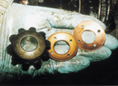
Carefully turn the nose of the differential again and watch the top and bottom gears move away from each other; one will come out at the front while the other tries to fall out at the back. Put you hand in to remove one along with the worn thrust washer and place on a clean cloth in the same orientation as it comes out of the axle. The other gear can be removed in the same way.
Now that the top and bottom planet gears have been removed the other two side planet gears can be removed one at a time, the worn fibre washer can now be taken out, replaced with a new washer and then the side gears can be re-installed in their location.
The top and bottom gears now need to be replaced. The easiest way to do this is to turn the nose of the differential until you can get a hand either side of the carrier. Then place the two gears opposite each other, hold in place and have an assistant slowly turn the nose of the differential again. You are aiming to be in a position to look down the hole where the main locating pin holds the gear in place and see all the way through. If you are a tooth out with the alignment one of the planet gears will not line up. If the gears are in the correct position then slide the new thrust washers into place between the carrier and planet gear. Once all the gears and washers are positioned correctly, drift the main pin back into position and secure in place with a new roll pin.
Reassembly
Ensure that the mating surfaces of the axle and cover are cleaned by removing old gasket, dirt and grease. Using a new gasket and sealer, then replace the axle cover, remembering the brake line clips at the top and handbrake pivot on the left.
The half shaft can be ‘felt’ back into position and making sure that the mating surfaces are clean, offer up the axle end cap and the back plate. Use the four bolts to pull the whole assembly together slowly by tightening opposite bolts a little at a time. Replace the coned spacer, hub and the castellated nut followed by the brake drum, which needs to be secured with the two Philips screws. The handbrake lever and cable can now be attached and the brake pipe screwed back into the wheel cylinder. Release the cling film from the master cylinder and bleed the brakes. If you are lucky you may only have to bleed the side you have removed the pipe from, however if the brake pedal feels spongy then bleed the whole system. Re-set the rear shoes by using the adjuster on the back plate.
Refill the rear axle with EP90 gear oil until it drips out of the filler hole, replace the road wheels, earth lead and then lower the car. Now the car is on its wheels the hub nut can be fully torqued up to 150 lb/ft and a locking split pin bent into place.
Clonking from the axle should now be much reduced, or barely audible. However, if there is no improvement, then providing you have checked hubs, wheels and the propshaft universal joints you may need to consider a replacement axle.