Problems with Percolation
Explanation
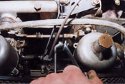
| If you mention the word percolation most people will assume that you are talking about brewing up some coffee, however if you have ever suffered from the problem you will recognise the symptoms. It may also be described as fuel evaporation or sometimes fuel starvation. The explanation of this problem is that the fuel gets so hot that it actually boils, thus causing the introduction of air into the fuel system. As everyone knows an engine will not run without fuel and you are left lurching up the road like a kangaroo as your fuel supply cuts out, then recovers, then cuts out and so on. | Undoing the throttle cable |
| This evaporation most usually occurs during the summer and will not be noticed until after a run in the car, you park up briefly, let’s say for filling up with fuel. On returning to the car you find it very difficult to start and when moving off you kangaroo up the road until the air in the fuel lines has been pushed through by the fuel pump. In extreme cases during hot weather you may even find that while trying to pull away from a junction or traffic lights the car will splutter and cough at anything other than the slightest opening of the throttle. In this article we are going to look at an MGA 1600 but the basic procedures and cures will apply to any car that suffers from percolation. |
 Releasing the throttle & choke cable bracket |
Possible causes
| The objective of the exercise is to reduce the amount of heat to which the fuel lines, filters and float cambers of the carburettors are subjected. The easiest job is to look at where the fuel lines run. If the main feed line to the engine bay comes straight past the exhaust system then it should be routed a different way, as you are making problems before the fuel arrives to the carburettors. | 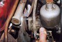 Sliding out the carburettors as one unit |
Deciding what to do
| After an inspection of the engine bay it was decided to replace the fuel lines, heat shield, fuel filter and wrap the exhaust manifold in a material designed to reduce radiated heat. To wrap the manifold requires the removal of the carburettors. Release the inner throttle cable from the throttle linkage using two 7/16″ spanners (see photo 1). Once loosened the outer cable can be taken hold of and both inner and outer cables pulled away from the linkage and curved back out of the way. The same can be done to the choke cable. Remove the pipe for the distributor vacuum advance and retard. With all the cables out of the way the bracket which holds the outer cables and fixes onto the inlet manifold can be removed to allow the carburettors to be taken off as one unit (see photo 2). Using a 9/16″ spanner undo the four bolts which hold the carburettors onto the inlet manifold. Be careful here as while undoing the bottom two it is easy to drop them and spend many minutes on the floor trying to find them. The whole carburettor assembly can now be removed as one unit using the throttle linkage to keep it all together, just push them gently towards each other and all will stay together (see photo 3). With the carburettors out of the way the heat shield and spacers can all be removed by sliding them straight off the fixing studs. |
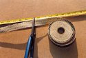 Cutting the exhaust wrap to size |
Wrapping the exhaust
| The manufacturer of the exhaust wrap claims that it will increase power, provide a more efficient engine and reduce under-bonnet temperatures by 70%. We are only interested in this case in the reduction of under-bonnet temperature so any other gain is a bonus. With many top racing teams using it to bring down temperatures it must work, so we decided to give it a go. | 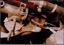 Fixing the start of the wrap with special clip – mind your fingers |
There are various types of exhaust wraps available on the market in different widths and lengths. We chose a inch wide fifty foot roll which came with an instruction leaflet on fitting. Also included was a conversion chart so that the correct length of wrap could be cut for each primary pipe of the exhaust manifold depending on the length and diameter of the pipe.
Before starting to work on the exhaust it is a good idea to block up the holes of the inlet manifold with some masking tape to stop foreign material making it’s way into the engine. Using the conversion chart cut the correct length of tape to wrap the pipes required (see photo 4). Start wrapping at the top of the pipe, just like a bandage and after the first time round secure with a clip (see photo 5). For this you could use worm-drive clips but because of the heat and vibration in this area it is suggested that stainless steel clips specifically designed for the job are used and these can be purchased with the wrapping. Once secured by a clip at the start just go round and round the pipe overlapping by about 1/4″ each time round (see photo 6) until the whole length of the tube is covered. When all is covered secure at the other end with another special clip and repeat on the other pipes.
CAUTION The clips used on this wrap were a self build cut to length type. They were very sharp once cut, causing more than one wound to the hands.
Replacement of heat shield
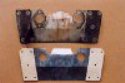
| Having inspected the heat shield it was found that the insulation was flaking off and the main metal body had severely dulled. Comparing it to a new shield there was only one choice – a new one was fitted (see photo 7). This is a simple operation, first clean the surfaces of the inlet manifold (after removing the protective masking tape), slide on the two new gaskets, then slide on the new heat-shield, slide on another two gaskets and finally slide on the cleaned up spacer blocks. | 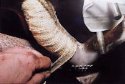 Wrapping the pipe – overlap by about 1/4″ |
Shielding the float chambers
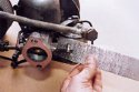
| Along with the exhaust wrap you can also purchase adhesive tape which both reflects and insulates from heat. With the carburettors still off the car now is the ideal time to protect the float chambers with this tape. Simply clean any oil and grime off of the float chamber, dry off and wrap a length around until it overlaps by about 1/2″ (see photo 8). It will then be necessary, depending on the width of tape used, to put another length around to completely cover the chamber. Due to the heat in this area it is advised to use a clip, similar to that used for the exhaust wrap, as a ‘belt and braces’ way of making sure all stays in place (see photo 9). |
 The difference between old and new |
Refitting carburettors
| With the heat shield and reflective tape on the float chambers in place the carburettors can now be replaced as one unit in a reversal of the way that they came off, again taking care not to drop the nuts and washers while doing up the bottom two fixings. Care must be taken when reconnecting the choke and throttle cable to ensure that when they are both in the closed position in the car (i.e. choke fully in and throttle pedal in ‘at rest’ position), the engine controls are also closed ( i.e. the choke is completely off and the throttle linkage is slack. Do not forget to reconnect the vacuum pipe to the distributor. If during the proceedings you have had course to split the carburettors or do any internal work to the carburettors you will have to check both the mixture and balance of them as detailed in the workshop manuals. a ‘belt and braces’ way of making sure all stays in place (see photo 9). |
 Adhesive reflective tape being applied |
Fuel pipes
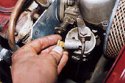
| The type and condition of the fuel pipes fitted to your car will determine whether or not you decide to replace them. This particular car had very old looking woven reinforced fuel line which had seen much better days. The correct type metal braided reinforced fuel pipes were obtained and we compared the old with the new. The old pipes were removed by undoing the brass unions on each carburettor. As the union comes off you will find a small filter which can be cleaned while the union is off (see photo 10. Replacement of these pipes is a straight forward task of undoing one pipe and replacing it with a new one, making sure that any fibre washers are either replaced or reassembled in the same order as removal. Care must also be taken to avoid any naked flame or other source of ignition while working with fuel lines and potentially explosive petrol vapour. |  All back in place but note the clip on the float chamber |
Start up time
| With all the new parts in place and nuts fully tightened, turn on the ignition. The fuel pump will run until the whole system is full and at pressure, now check all the junctions in the fuel system for any leaks. This must be done very carefully due to the obvious risks. When you are happy that there are no fuel leaks then start up the car. Run the engine up to normal temperature and you will find that the exhaust wrapping will start to smoke. Although this can be slightly alarming, it is quite normal. You will find that after about five to six miles on the road the smoking and associated smell will have gone. |
 The small built-in filter |
| You should now be able to go out with peace of mind knowing you have taken steps to prevent fuel percolation and that you can enjoy your car to the full. | 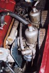 An engine bay with the carburettors protected against heat |