Fitting a Kenlowe Fan
to an ’72 (Chrome Bumper) MGB
A Kenlowe fan is a useful addition to your MGB for a number of reasons:
- a) Removing the original engine driven fan reduces drag and this will slightly increase the power available to drive the rear wheels.
- b) With the original engine driven fan removed, the engine will warm up more quickly as there is no constant cooling effect. This will save fuel, wear on the engine and the faster warm up time will be appreciated by the driver and passenger when using the car in the winter months.
- c) In particularly hot weather or perhaps when towing, the original fan can be kept in situ and the Kenlowe fan can act as an additional cooling aid.
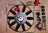
| It is wise before starting to fit the fan to check that all component parts are in the kit (there is a contents check list in the box). | Kenlowe fan kit. |
Removing original fan
Job number one is to remove the original cooling fan fitted to the water pump housing at the front of the engine. This task is quite straightforward – simply slacken off the alternator and remove the fan-belt. Once the belt is removed, use a 7/16″ ring spanner undo the four bolts that are holding the fan and water pump pulley to the nose of the water pump. There is very little working space, so be careful not to rap your knuckles on the radiator matrix for fear of damage to the matrix (or yourself!). Separate the fan from the water pump pulley and refit the latter by using the same fittings. Replace fan-belt and re-tension as appropriate.
| Assembly It is necessary to assemble the fan before attaching it to the MGB. There are full instructions in the box but they apply generally to all cars and not specifically to MGBs. I found it easier to assemble the whole fan, including the mounting brackets, before offering it up into position. This was done by attaching the D shaped lugs to the motor using the bolts supplied. Although not mentioned in the instructions, I would suggest using some thread lock to stop them undoing. Make sure that the bolts are passed from the spindle end through to the lugs as this ensures that the fan will not catch on the bolt ends. Attach the plastic C clamps to the D lugs, using the bolts supplied and in the order recommended in the instructions, then pass through the L shaped aluminum tubes. Finally, slide the last two plastic C clamps onto the aluminum tubes. |
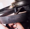 Fixing D brackets to fan motor. |
Fitting the fan assembly
The manufacturer recommends, if possible, that you fit the fan on its brackets using two different mounting panels. However on an MGB this is only possible after modifications, therefore it is best to use the bottom radiator panel for both brackets.
| The Kenlowe fan sits right at the front of the car, fitted between the radiator and oil cooler. Now offer up the assembled unit to establish positioning. It is best to mount the fan as close as possible to the radiator matrix but it is also important to allow 1/4″ gap between the fan blades and radiator, taking into account the header tanks, radiator cap and the shut line of the bonnet. Take note also that the wires on the fan motor should point downwards (or as near as possible) as this acts as a breathing/drain point. | 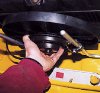 Offering assembled fan into place. |
| Once happy with positioning, mark where the two bolt holes lie on the bottom radiator panel for later drilling. Be careful here – there is a line of spot welds on this bottom panel, so if possible try to position Kenlowe fan on the radiator side of these. This is because there is a strengthening section forward of these spot welds and therefore more difficult to pass bolts and nuts through. | 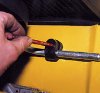 Marking the fixing holes before drilling. |
| Now that the two points are marked, drill a small pilot hole and then enlarge them to a 5/16″ hole. Pass the remaining two fixing bolts though these holes and fix the whole fan assembly onto the car again paying attention to the way the plastic C clamps are assembled. | 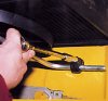 Tightening the fan into place. |
Finally check that the fan blade will rotate without hitting anything. The bolts can then be fully tightened (take note of the manufactures’ instructions with regard to the plastic C clamps as if over tightened they can b reak). The last job is to screw in the cross-head screws into each of the C clamps, this stops any movement caused by vibration of either the fan or car engine. The thermostatic control can now be fitted.
Fitting the thermostatic control
This unit has to be positioned near to the top hose of the radiator. On this MGB the best place is on the radiator diaphragm panel on the right hand side as you look at the engine from the front. Due to space consideration I would suggest the front of this panel rather than the rear (it is best to have some room to work around the carburettors).
| Attach the mounting bracket with the self tapping screws supplied, making sure that when in position, the assembled unit is low enough for the bonnet to shut without interference. The thermostatic unit can now be mounted onto this bracket fixing with the nut supplied. | 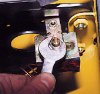 Fixing the thermostatic control to mounting bracket. |
| Take great care at this point because the copper tube on this unit is delicate and can become work-harden and will then break quite easily – once broken it has to be replaced and this can be quite expensive. Once mounted the thermostatic unit needs the control knob fitting and the locking screw put in place. |
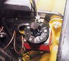 Adjustment knob and locking screw. |
After making sure that the engine is cool, slowly release the radiator cap, undo the hose clip around the radiator end of the top hose and pull the hose off, draining the water that will come out into a container. Now is the time to be very careful. Gently feed the copper bulb and some of the pipe through from the front of the radiator (via the gap between the radiator and the radiator diaphragm panel) to the top outlet of the radiator. It will then be necessary to put a ‘U’ bend in the copper pipe so that the bulb is pointing into the radiator.
Place the rubber block supplied onto the top outlet of the radiator, then put the copper tube in the grove of this block. Carefully slide on the top hose and fasten the hose clip. – make sure at this point that the rubber block has not moved and there is a good seal between the hose, copper pipe and radiator outlet. The water level should now be topped up.
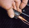 Copper bulb and rubber block held in place. |
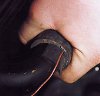 Sliding on top hose. (optional) |
Wiring the thermostatic control
The thought of working with electric wiring can often discourage people from attempting to fit any equipment to their car. In this instance the wiring is straight forward with the manufacturer supplying very clear instructions. Locate a live supply from the fuse box which is controlled by the ignition switch. The feed be taken from the fused side of the box. With the ignition switched off use a volt-meter to try each terminal of the fuse box to establish which are live – these can then be ignored. Now do the same exercise with the ignition switched on – use one of these terminals as a power feed. (I used the second terminal down).
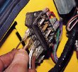 Connecting up live supply |
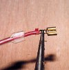 Crimping on terminal. |
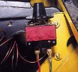 Wiring clearly marked on thermostatic control. |
Crimp on a female spade terminal to one end of the red wire as supplied. Attach the wire to the live terminal on the fuse box and run down to the thermostatic control unit, following the car’s main wiring loom. Cut to length, crimp on another terminal and connect up to the terminal marked ‘connect to power supply’.
| Using the same procedure run a wire from the terminal marked ‘fan motor’ on the thermostatic control to one of the fan motor wires (the fan motor wires have a bullet type of connector).The final wire to put into place is the second wire of the motor which needs to be run to a convenient earthing point. Now this is all in place make sure that all the wires are clear of the fan blades and switch the ignition on, turn the black knob on the control unit until the fan motor starts. Using a strip of ribbon or similar place in front of the fan to ensure it is blowing in the correct direction i.e.through the radiator and not out the front of the car. Turn the adjusting knob until the fan stops and switch the ignition off. Use some cable ties (not in kit) to tidy up and secure all wiring. |
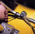 Tidying up wiring. |
| Setting thermostatic control Start the engine and warm the car up. Check that there are no water leaks from around the top hose. If there are any leaks it will be necessary to let the engine cool down and then refit the copper tube into the top hose. The fan is adjusted by turning the control knob in the appropriate direction to allow the fan to cut in at either a higher or lower temperature. Keep a eye on the temperature and adjust the fan until it cuts in with the temperature gauge reading slightly above the car’s normal operating temperature and out again at about normal on the temperature gauge. Once the right balance has been reached lock the knob by tightening the locking screw. |
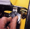 Final adjustment of fan. |
| The fan is now fully fitted and should require no maintenance except for an occasional check on the seal where the copper tube passes into the top of the radiator. One last word of warning, if the engine is running and you are working in the engine bay, be aware that the fan can cut in and out without warning – getting your fingers caught in the blades of the fan really hurts! |
 |