Revival of an Old Friend Part 4 – Fuel injection
This subject has been a favourite of mine ever since having to find out the dark secrets of EFi when first looking to use it all those years ago, and finding that it wasn’t such a black art after all. This may have introduced me to EFi sooner than if I had waited for it to become common, but experience illuminated the advantages of using EFi and better still, full engine management control, whenever possible. Today there are many specialists able to provide a full one off installation with total user control and with amazing system functionality, a complete contrast to the crude and simple EFi of the 1980s.
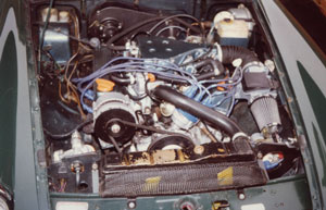
MGB V8 EFi fuelled by Lucas Airflow Meter (flapper) injection system
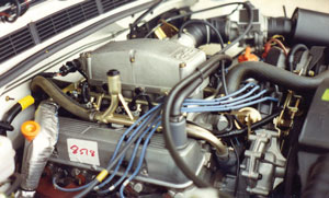
Range Rover with Hot wire fuel injection where there is plenty of head room for the system
Today most vehicles are managed by several computers to provide cleaner, lower emissions and greater public acceptability. This was in mind when planning the change to my injection system as I wanted to increase efficiency, get more miles per gallon and if there was a power bonus then fine. I already felt that the power and torque levels were ‘adequate’ for more than reasonable performance. The new system also has the facility to fit two cats, a pair of Lambda sensors and plug in the retained wiring connections, add one further control system change to activate the cat spec mapping and I can immediately meet Euro 1 levels (RV8 level) and with a little further work probably Euro 2 specs.
My original Lucas Airflow Meter injection system is based on the early Bosch ‘flapper’ type airflow meter systems and was still pretty leading edge at the time I fitted it. Leading edge in computing terms is also known as the ‘Bleeding edge’ for reasons related to more problems affecting newer systems. Fortunately when I started with the Lucas EFi system the edge was rather blunt, so it led to only minor cuts.
By the 1990s the rapid development in engine management meant the ‘flapper’ system, with analogue control parameters, was far from leading edge and that worthwhile additional efficiency gains appeared out of reach. Not that it was bad to start with, as during the initial running in period an out of balance propshaft dictated a maximum bearable speed of approx 58mph and that a 100 mile run returned a genuine 38mpg, which plummeted as soon as the propshaft was rebalanced.
Late in the 1980s Land Rover replaced the ‘flapper’ type system with the more efficient Hot Wire system for all injected V8 engines. As the Land Rover systems also used a variation of the ‘Vitesse’ style manifold, this dictated the obvious economic route to follow, plus this was on the RV8.
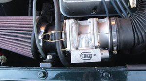
Hot wire system airflow meter
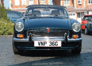
The highest priority since the very beginning of thinking about going V8 was to keep the standard MGB bonnet line
I was able to source a complete 1990 spec Discovery 3.5 litre injection system, along with its 14CUX ECU. I chose this route bearing in mind my engine is still a 3.5 litre one, not 3.9. There was then, and remains now, no point in changing an engine that provides more than enough power to embarrass the chassis for a larger displacement one. However, if I was to be starting again today I regard the ideal Rover V8 capacity is 3.9 litres (4.0 litre engines are the same capacity, but different in detail). 4.6 litre engines are in my view clearly less suited to the MG application without work and why go there when the 3.9/4.0 provides more than enough power and torque?
One of the first ECU changes was a custom EPROM that removed the Land Rover 112mph speed limiter, however without a road speed sensor this doesn’t activate. This is a common feature for all Land Rover vehicles where the top speed capabilities are higher than the speed rating for the tyres. The RV8 and my MGB do not have such tyre restrictions and when on tracks you do not want such restrictions. Interestingly I was recorded at 142.6mph in a speed trap before the end of the Bruntingthorpe test track two mile straight. More evidence to show why I considered the original engine adequate!
When I sourced the Hot Wire system the RV8 may have been very new, but this system was common so information was much easier to come by than ten years before with the Flapper system. As my car had been instrumental in moving the RV8 project on and it adopted a couple of features from my car I felt it only courtesy to adopt several of the new features of the RV8, the exhausts through the inner wings for example.
One RV8 aspect I did not want to follow was the bonnet bulge, and having made so much effort to ensure that my previous injection system did not require bonnet modification, I did not feel inclined to change this approach. Whilst the bonnet bulge on the RV8 is appropriate to that car it was not for a chrome bumper MGB. Aside from the attractions of fitting injection to a Rover V8, it is the convenience afforded by almost all of the injection system components being contained on the inlet manifold that makes the conversion of any V8 relatively simple. The only modification needed to be done to a standard non injection engine when fitting fuel injection is to create small cut outs in the top edge of the inlet ports at the manifold face to provide a clearer path for injector flow.
The Hot Wire system wiring was very similar to the previous Airflow Meter system, although more complex, and followed the same principles of being a separate stand alone loom. This allowed the same mounting position for the ECU, to the underside of the passenger footwell, in the dry and away from heat and moisture. Power feeds and relays were located close by and once again I adopted the route of adding a completely new additional battery power feed from the starter solenoid to a new fuse box with multiple relays.
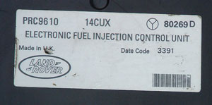
Lucas 14CUX Hot Wire ECU label. Land Rover part number PRC9610, Lucas part number 80269D and made during week 33 of 1991 line
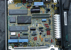
ECU cover removed to show circuit board and inner workings and under the plastic cover with ‘LUCAS’ is the EPROM…
The fuse box and relays provides power and protection for other non original electrical features, thus relieving any extra stress on the car’s original fuse box, a pretty basic and overstretched system in any case. I also renewed the main and rear wiring looms at this time as the original 1968 items were clearly past their prime, plus there were other additions I wanted to add, so I will come back to under the electrical section.
I achieved my desire to fit the rather tall injection manifold under a standard MGB bonnet and I don’t pretend to claim a first here as I had already seen other applications using a lowered Vitesse or Range Rover style inlet under the standard bonnet. My previous Federal Airflow Meter system manifold came in two pieces, already some three inches (75mm) lower than the later Vitesse (Range Rover and all later Injected V8s up to the ‘Thor,’ [Bosch] systems, of the late 1990’s). To get this early Federal Airflow Meter system in my engine bay I had approximately 12mm skimmed from the plenum top where it joined the lower manifold part.
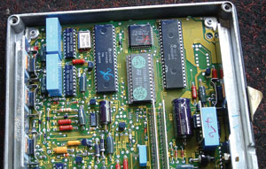
…which when removed shows the remapped EPROM with label indicating the road speed limiter removed
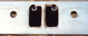
When fitting injection there is a need to modify non injection inlet ports in the cylinder head and this is for the injector spray path as shown here
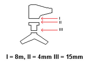
Schematic showing where and by how much material has to be removed from the inlet
However, the extra height in these later Vitesse and Land Rover type three-piece manifolds, plus that 12mm I skimmed off the original manifold would be 87mm too much to find and keep the standard bonnet. However, I was at this time using a V8 conversion type of engine mounting welded to the chassis, which clipped over the top lip of the chassis rail and so raised the fitted position of the engine quite substantially. I mentioned the reason for using these in a previous installment. By removing these and fitting the standard factory MG V8/Rubber Bumper engine mounting brackets the engine position dropped by approximately 60mm.
This also dictated the use of a Rubber Bumper crossmember to create sump clearance against the crossmember. I also had to change the original MG V8 pre SD1 sump to a later one, where the well of the sump is fully at the rear of the engine. Now I found that with the engine sitting in position with manifolds fitted that an extra 27mm was needed to be able to close the bonnet.
I nearly made a serious error here as I sat the engine on the original 10 year old, but apparently fine, engine mounting rubbers, which had in fact compressed a little more than at first appeared. I was fortunate that when finally fitting the engine with new rubbers, there was still 2mm clearance between top of plenum and underside of closed bonnet. That widened to a more satisfactory 5mm once the engine had run and settled, with some more since. If the issue had been tighter then I would have used the left hand RV8 engine mounting rubber as this is about a third thinner than the original GT V8 mountings. (Only used on the left side on the RV8 as the right side needs the thicker rubber for steering shaft clearance.)
To be continued…
Roger Parker