LUMENITION IGNITION SYSTEMS
It’s all about timing!
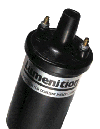
| Conventional contact breakers in our MG distributors start to deteriorate immediately after fitting and require changing at approximately six thousand mile intervals, by which time they are usually worn out. As they require accurate setting and are sensitive to wear it is not surprising to note that over 80% of breakdowns are attributable to electrical failure. Furthermore with ageing distributors the shaft is often worn causing inaccurate timing when the engine is running. By fitting one of Lumenitions’ electronic ignition systems that replaces the contact breaker and condenser, your chances of electrical breakdown are greatly reduced. Lumenition has developed three systems, all of which replace the standard contact breaker and condenser with electrical triggering devices with no touching parts so that wear is impossible. The ignition timing remains set with no need for subsequent adjustment and provides improved reliability over the standard contact breaker set-up.
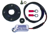
The most recent development is the Magnetronic ignition system that replaces the standard contact breaker and condenser by means of the established “Hall Effect” principle. Comprising simply of a magnetic triggering device and a unique miniature module, both of which are located neatly within the distributor itself. Magnetic inserts incorporated on a circular disc, one insert per engine cylinder and as the disc rotates on the distributor spindle, a monitoring module that is located beneath the disc produces an electrical pulse, switching the coil on and off and thereby producing a high tension spark at the spark plug timed precisely when required. As there are no moving parts to wear the engines’ timing remains permanently set with no adjustment necessary. MAGNETRONIC INSTALLATION |
connect. The following demonstrates the fitting sequence of the Magnetronic system.
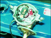
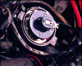
Fitting Tip: Magnetronic can be fitted the distributor in situ, however fitting is more easily carried out with the distributor removed. If removing, first mark the position of the distributor in relation to the engine block. Also mark the position of the distributor shaft in relation to its body. All marks can then be realigned on refitting. 1. NB. Disconnect the MG’s battery before commencing work. 2. Remove the contact breaker and condenser. 3. Locate the adapter plate in place. 4. Install the Magnetronic module, feed the wires through the hole and secure with the grommet. |
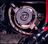 5. Fit the magnetic disc over the cam, ensuring that the eccentric depression indicated by a dot aligns with the rotor arm tip. (Note point seven on the fitting instructions supplied)
|
| OPTRONIC INSTALLATION
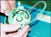
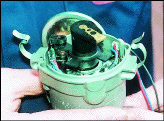
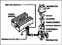
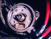
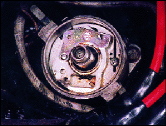
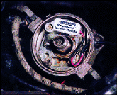
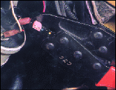
Unlike the Magnetronic system, Optronic ignition utilises a light emitting diode optical eye switch opposite a matching silicon photo-transister between which an infra red beam is passed and this is by far the most accurate method of switching possible. 1. Disconnect the cars’ battery and observe the fitting tip regarding marking and removing the distributor as shown on the Magnetronic fitting procedure. 2. The photo shows the standard contact breaker and condenser, both of which should be removed along with the rotor arm. 3. Fit the optical switch to the original contact breaker mounting hole and pivot pin using screws and washers provided. 4. Locate the chopper fully down on the shaft ensuring that the chopper passes centrally through the optical beam and also that the blades clear the capstan pin formerly used for securing the old contact breakers. On some early distributors it may be necessary to shorten the height of the capstan pin to enable the chopper blades to clear. |
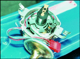
5. Attach the connecting plug to the three wires.
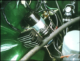
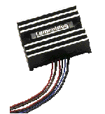
6. The photo shows the power module on its fixing bracket located adjacent to the coil and the black earth wire attached as shown. The Red wire can then be connected either to a) the feed side of the ignition terminal on the fuse box or b) the ignition switch side of the ballast resistor for 1974 onwards models, or c) to the ignition terminal of the ignition switch, but do not use the auxiliary terminal that switches off when in start cranking position. Finally connect the brown wire to the wire from which the contact breaker assembly was
|
removed. This goes to the negative terminal of the coil, sometimes in earlier cars via the tachometer.
7. Fit the red connecting plug and link the power module to the optical switch. Replace the distributor in line with the marks made earlier and slightly tighten the pinch bolt to allow for final adjustment. Refit the cap, leads and reconnect the battery. HIGH PERFORMANCE CONSTANT ENERGY For details of members’ discounted prices on all three Lumenition systems, refer either to the Offer leaflet enclosed with this magazine edition, or telephone MG Owners’ Accessories on 01954 231318.
|