MGB Heaters
Most MGB owners will acknowledge that the heater’s output is usually somewhat weak. Although in a very small number of cases an MGB can be found with a heater as efficient as that of a Ford which just proves that these heaters can be made to work, so the question is what can be done to improve them.
Various upgrades have been offered over the years but it wasn’t until the MG RV8 arrived in 1992 with a modified heater that Rover made specific mention that the RV8 heater was able to deliver 5.5Kw of heat output. A five and a half bar electric fire output was impressive and experience shows that the RV8 leaves almost every MGB literally in the cold.
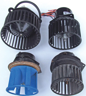
Heater fans, standard – lower right, Costello – lower left, uprated upper left (upper right an early prototype)
To have an efficient heater you need to have good hot coolant flow, an efficient radiator to exchange that heat to air, and strong well controlled airflow through that heater to get the heated air into the car.
Standard MGB heater radiators (often termed a heater matrix) are big enough to exchange heat from coolant in sufficient quantity to provide more than adequate heat, proven by the odd standard MGB with an effective heater. However, most MGBs suffer a variety of problems that restrict the internal coolant flow and affect the heat exchange efficiency. As the heater radiator has the smallest holes this clogs first it is the primary area to ensure there is a good flow rate. Other restrictions can be in the heater control valve where this attaches to the B series engine sometimes the casting is poor and restricts coolant flow to the heater valve.
For many years uprated heater radiators have been available that offer improved heat exchange, so when a heater radiator needs to be changed for whatever reason then fitting to an uprated one is a positive move. However, the point has to be made that no single change is going to turn the MGB heater from a campfire into a volcano, but a matched series of checks, changes and upgrades can turn that camp fire into a bonfire.
Looking at the airflow reveals a problem affecting many cars. This relates to the simple fact that for the air to become heated it needs to pass through the heater radiator. Air like other natural substances, such as water, will flow along the easiest route available and here we must realise that passing through a radiator core will provide resistance to that flow, so if there is an easier route for air to take it will follow that. In such circumstances the heater radiator may be really hot, but if the air doesn’t pass through it, very little heat will find its way into the car.
The heater box may present a well controlled space from an external perspective, but one common failing is that the heater radiator sitting inside the heater box is much smaller than the inside space. To help force all airflow through the radiator nothing more technical than foam is wrapped around the outside of the radiator to fill the gaps between the heater radiator and the heater box leaving air no option but to pass through the heater radiator. A common problem is that over time this foam degrades and crumbles into dust. Before going into detail on the uprating of the heater fan, it is more than prudent to consider all the points mentioned so far as the work I will cover relating to the fan will demand partial removal of the heater box from its seated position, and opening of the front. Both the heater radiator and the foam seal will be accessed at this time and so logic says that if you’re looking to change one part then unless you know the other internal parts are nearly new and in good condition, replacing these whilst access is available makes sense.
Heater fans
Airflow for the MGB heater (or fresh air unit that can be found on some earlier cars, a heater box with fan and no heater radiator) comes through the chromed grille that sits immediately in front of the centre of the windscreen. It is positioned there as that is known to be a ‘high air pressure area’. This translates to very simple physics and as the car drives through the air it has to push the air out of the way. The windscreen presents a large surface area and so much air has to be moved and in doing so air builds up immediately in front of the screen until it is moved aside. By placing the air intake there it takes advantage of this pressure build up and positive airflow passes into the heater box without the need for fan assistance, although we all know that it is not that strong a flow. It will also not be a coincidence that generally the GT has better ram effect flow than a Roadster and that relates to the greater height of the windscreen blocking more air and so increasing the pressure over the heater air intake grille.
Generally to get a reasonable airflow through the heater system we need the assistance of an electric fan. Most MGBs have a single speed fan and it sits at the one end of the heater box with the fan impellor inside the heater box and the motor sticking out into the engine bay. Once again over the years we have seen a range of improved fan designs, which have come with mixed results.
The first element to look at is the motor, and specifically having one with enough torque and rotational speed to drive the impellor fast enough to move a reasonable volume of air. It is quite surprising how a small drop in motor speed reduces the air flow rate by quite a margin, trouble is that unless you have another good fan motor to compare with it is virtually impossible to judge anything other than a clearly failing motor.
Another aspect dictating airflow is the design of the fan impellor blades. In standard form the fan has a pretty small diameter that enables it to be fitted to the motor and then the impellor passes through the hole in the heater box making assembly and servicing simple. The downside is that the volume of air that can be moved is restricted. The other point is that the space in which the impellor is located is much bigger than the impellor itself, leaving room for some air to simply circulate around inside the box rather than follow the desired path.
The shortcomings of this fan have been known for many years and several uprated impellor designs have appeared. Quite a few years ago I fitted an uprated ‘Costello’ impellor to my car (the blue one in the images) and I can recall the change from hardly any detectable airflow, to obvious airflow, although it was still not great. Even though this new fan delivered an improved flow it was still only a light breeze rather than a gale.
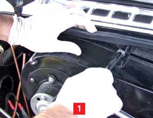
Remove upper nut…
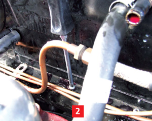
…and screws in lower flange
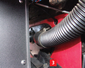
On some cars it will be necessary to loosen the lower demist pipe connection plate behind the speaker centre console…
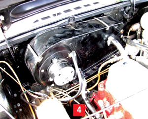
…to ease the heaters move upwards, which just needs to be 30 to 40mm
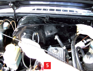
With hose connections removed the clips holding the heater front to the body can be removed and the front slipped off
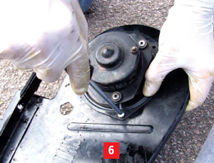
Original fan can be removed earlier if desired, but if screws are tight it is easier to remove these when the front is off
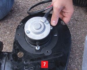
The new motor is placed on the front panel and new fixing screws used. The screw holes allow a little movement and it is best to push the unit as far as possible to the 10 o-clock position, when looking at the front as it fits in the car
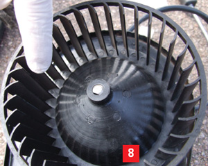
Motor fitted and impellor is pushed on so the end of the motor shaft is level with the end of the impellor
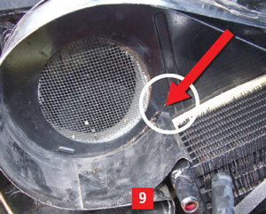
Inside of the heater box showing the ‘ski ramp’ and the spot weld that may have to be drilled out arrowed
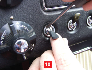
The original single speed heater fan switch is removed
There remains a little more scope to improve airflow which involves a stronger motor fitted with a much larger impellor. This impellor is designed to fit all the available internal space and with the bigger diameter comes an ability to move more air, plus reduce its tendency to simply circulate. Increasing the diameter of the impellor increases the volume of air that can be moved but also demands more power to turn the impellor. This is partly why using the more powerful motor is an integral part of the conversion, another aspect being the advantage of being able to reach higher rotational speeds. Higher speed and greater airflow also brings with it the opportunity to make an effective two speed operation, somewhat better than the later MGBs two speed fans. This subject I will return to later.
Fitting
Removing the original fan and motor as a complete item is quite simple but the larger diameter fan can’t be fitted through the existing hole in the front heater panel. The heater box front panel has to be removed for the required access and to do this you will need to partially lift the heater box assembly around an inch or so from its location in the bulkhead. In the case of the donor car this was simple because the heater had previously been removed not long before, but most cars will have had the heater in place for many years and in truth heater removal is one of the less attractive jobs on an MGB.
There are a series of fixing screws around the base flange of the heater that are often corroded and sometimes difficult to remove, and also a single upper bolt that holds the top of the heater box against the bulkhead. The two rubber hose connections to the heater radiator will also have to be removed, so expect some coolant spillage.
A small lift is enough to allow the series of spring clips holding the front face to the body of the heater to be removed, and then the front to be lifted off, without the complication of having to disconnect any of the lower pipe and cable connections that run from the depths of the heater assembly into the car, although many heater box assemblies will still be extremely tight to move, even when all the fixings are undone.
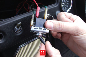
The new two-speed switch is wired before…
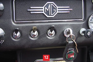
…replacing the single speed switch and looking standard
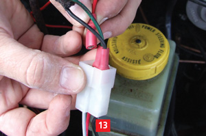
Wiring connected to the motor plug, the red wire is the additional one for slow speed
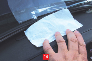
Crude airflow test showing standard fan airflow
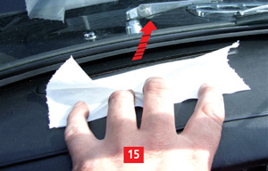
Crude airflow test showing the improved ‘tissue lift’ of the uprated fan and motor
Unfortunately the front face of the heater box continues below the top of the bulkhead, which demands the heater be lifted to remove this face. With the heater front face off the car you can address any internal changes mentioned earlier, followed by fitting the new motor to the front panel. Once the motor is loosely fitted via its three fixings, the impellor is slid (pressed) onto the motor shaft until the end of the shaft is level with the engine of the fan centre.
Now because the impellor is designed to utilise almost all the available internal space and the original fan had acres of space when fitted, you need to fully tighten the three fixing screws and offer the heater front back onto the heater box, temporarily connect the motor to operate it and check for adequate clearance for the impellor. There may be slight contact with what looks like a ‘ski ramp’ inside the box. If this is present then firstly the three motor fixing screws should be loosened and the motor moved within the available float in a 10 o-clock direction and the screws tightened.
It is possible that the motor adjustment will not be enough and it may be necessary to twist the ‘ski ramp’ slightly. In extreme cases the single spot weld holding the ‘ramp’ to the back of the heater box may have to be drilled out to allow the ‘ramp’ to be twisted further. Refit by drilling a new hole in a suitable position in the heater box and re-secure the ‘ramp’ using a small stubby self-tapping screw.
Two Speed Fan
At this stage the heater can be reassembled, but if this is being fitted to a later MGB the opportunity can be taken to remove the original heater resistor that provided the two speeds for the standard fan motor. The common method of giving two speeds was to have two power feeds to the motor with one passing through a wound wire resistor to lower the voltage and thus operate the fan at approximately half speed. This method generates heat in the resistor and mounting inside the heater box provides a steady airflow to keep it cool. The new motor has a more efficient internal method of providing the twin speeds and so this resistor is redundant. Once the resistor and wiring is removed, a small bung is used to fill the hole.
If just a single speed fan is desired then the original wiring and switch is retained and the green/brown power feed (earlier cars) or green/yellow (later single speed cars) is connected to the red wire of the new motor. For earth the black from the car’s wiring is connected to the black of the new fan motor. New spade connectors will be needed to be fitted on the car’s wiring for the simplest fit, although many may want to trim the wiring lengths to suit their car and make new connections to suit or match the original wiring connections.
For those wanting two speeds then they will need a new two-speed switch, toggle or rocker type to suit the age of car, and then to lay in a new length of wire between the switch and motor and connect to the motor’s grey wire. Essentially the two-speed switch provides the same 12v power along both wires and it’s the internal circuit in the motor that dictates slow or fast speed. Connecting the wires at the switch to give the correct first ‘on’ position for slow speed and second ‘on’ position for the fast speed is simply a matter of following the same pattern as shown in the image, which for the donor car used pin 4 for power feed in, 6 for slow fan speed, and 8 for fast fan speed.
There are variations for this and it is not at all critical which pins the wires connect to as these switches are just distribution points and you can’t do any damage, you get different switch positions for the fan operation. Trial and error fitting will sort this out.
Lastly the later cars starting with the factory two speed fans just need the original three wires feeding the old fan motor to be fitted to the new fan motor, green/brown to grey, green/yellow to red and black-to-black.
Results
It is somewhat difficult to accurately quantify how much difference the new fan and motor makes, but it is quite noticeable. I did a crude test before fitting between the standard fan/motor, my Costello uprated fan/standard motor and the new uprated fan/motor. I locked each down in the same place and ran each from a slave battery. I put a hand into the airflow and moved it away until I could no longer feel the airflow, I moved about 14” for the standard fan, about 16” for the Costello version but about 21” for the uprated fan/motor, hardly scientific but a useful indicator.
On the donor car I used a piece of tissue that was held over one of the screen vents which with the standard fan before starting managed to lift the tissue off the vent. After fitting the uprated parts the flow was folding the tissue back on itself (images 14 and 15) again this was not exactly scientific but another good indicator of much better airflow.
Roger Parker