MGF Front Lower Arm Replacement
MGFs are ageing well in most respects with the majority of them having now passed through the premature head gasket failure stage. However, age brings other issues and unlike older classic MGs where almost all problems are well known and documented, the MGF is still going through its first life cycle and new problems emerge that need new solutions.
The problem is obvious!
Rust is one of those four letter words deeply engrained in the minds of classic MG enthusiasts, but not so with those brought up with MGF and newer MGs. However, whilst the MGF does not yet have any reputation for serious body corrosion as the standard levels of anti rust treatment were good; there are a few chinks in its armour.
Subframes and suspension components do not have the same rust resistance properties as the body, this is revealed in those basic steel items that only have a thin coat of unimpressive black paint. Subframes are the biggest items but they are so rigid and thick that it will take some more years before they have any structural problems. The same applies to items like the anti-roll bars, the front especially being low and exposed to the sand blasting effect of road dirt etc.
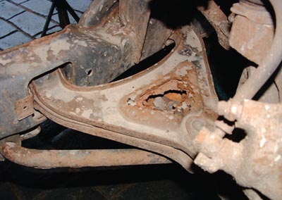
In a similar area are the front suspension lower arms, a sandwich of two steel pressings welded together to make the lower arm which is then painted. Look at the images of a typical pair removed from a 1996 N reg car with an apparently average life history. Both the upper halves of the lower arms had rusted right through and whilst this may not show the same large holes initially, gentle probing can reveal the crumbling beneath the surface.
Obviously this is unacceptable for safety reasons; also it should be picked up at MoT time by attracting an immediate failure. However, for peace of mind owners of older cars with some obvious ‘crustiness’ on this area should probe it with a screwdriver or similar. Being harsh with probing is not an issue here as this metal has to be sound and if any penetration is achieved then this is the signal for replacement.
Official MG factory replacements for mainstream MGFs are not available, as they have been superseded to the TF unit, although pattern parts are very widely available.
The oddity with the MG factory (Xpart) parts is that the rear inner pivot bush is a different spec on the TF to the MGF, plus the MGF spec bush is also no longer available. Thus when looking to replace a single lower arm you are faced with the need to replace both arms to the newer TF type. If there is really nothing wrong with one arm (perhaps it had been changed not too long ago) it is galling that the official parts route requires both to be changed with the final sting in the tail being the need to spend well over £100 for an arm you don’t need.
Of course this opens the door to the opportunity to replace all the suspension bushes with one of the Poly bush kits and follows the age-old MG tradition of replacing worn components with uprated parts. Many enthusiastic owners over nearly the whole life of the MGF have gone down the route of fitting replacement bushes. It’s also common to fit lowering knuckles that reduce the oft described ‘Freelander’ ride height to something that looks more sporty with approximately only a 35mm drop and still enough clearance to negotiate Local Authority official assault courses.
One final oddity in the lower arm supply saga is that the MGF Trophy 160 SE models’ lower arm is still listed as available and at a list around a third of the retail price of the standard arms. The arms are the same and it’s only the bushes that show a variation. Here though it’s not the bush itself that is different, but the fact it is inserted into the arm differently with the position rotated 90 degrees and this generates greater stiffness.
Anyway once the arm and bush decisions have been made it’s back to fitting the replacement arms. On paper this is quite simple except for one big fly in the ointment around the removal of the rear pivot bolts. Put simply the rear bolts for the arms can’t be removed until the subframe is lowered.
How to carry out the job
Firstly loosen the road wheels for easy removal once the car has been raised comfortably high and axle stands specifically placed underneath. As the subframe itself has to be lowered the axle stands can’t be placed under any part of the subframe but fortunately the car’s body is suitably reinforced just behind the subframe’s rear body mounting. This provides enough room for the stands to fit and still allow the subframe mounting to be loosened and the subframe to be subsequently dropped.
Once the wheels are off, chock the upper suspension arm to reduce the downward suspension pressure as this makes dismantling easier. Chocking the upper arm is done by jacking up the suspension one side at a time until the car is starting to lift off the axle stand on that side. You can lean on the wing gently to settle the suspension a little more, and then you insert a flat wedge, a cold chisel is ideal, between the underside of the upper arm and the rubber bump stop. When the jack is lowered the wedge means the suspension doesn’t settle as low as it would in full droop and gives an easier time when it comes to strip down.
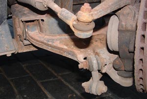
1 Lower arm rear bolt can’t be removed because the body restricts movement
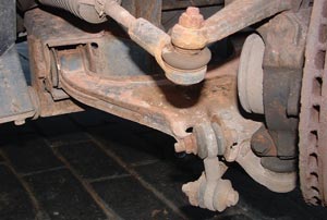
2 Anti roll bar drop link, remove the upper bolt to the lower arm
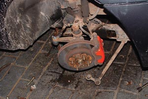
3 When both anti roll bar drop links are disconnected pivot the bar down
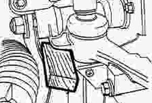
4 Jack up suspension and chock the upper suspension arm
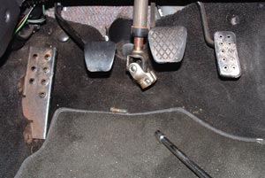
5 Remove steering column to rack pinch bolt and disconnect column
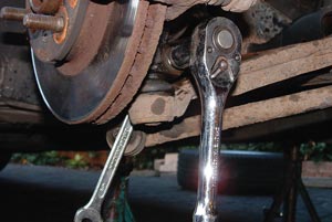
6 Remove lower ball joint to hub pinch bolt
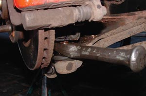
7 Separate lower ball joint pin from hub
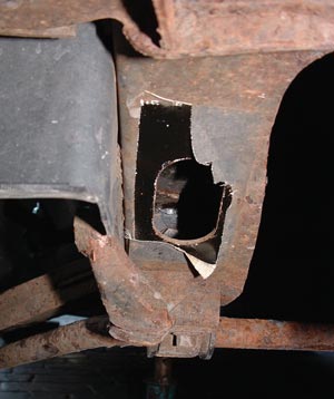
8 Expose access hole for lower arm front pivot bolt
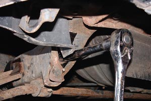
9 Use long extension and socket to undo and remove front lower pivot bolt
Don’t worry about damage to the bump stop as you’re only substituting one flat bit of metal resting on it (cold chisel) for the underside of the arm. Repeat this operation for the other side.
The strip down starts properly now and before you get too dirty crawl into the footwell of the driver’s side, mark the bottom of the steering shaft and the rack pinion for refitting reference, and remove the lower pinch bolt. Lift the lower column joint off the pinion shaft.
Outside now, remove the anti roll bar link bolts to the lower arms on both sides so the bar can be pivoted down and out of the way. Next remove both front damper lower bolts noting the positions of the spacer and large washers for correct refit. Remove the bolts so the dampers are left hanging free. The workshop manual also advises removing the anchor bolt for the brake hose, but I have found that the degree of movement required to lower the rear of the subframe doesn’t stress the brake hose. However, this is something to keep an eye on when lowering the rear of the subframe.
Now the lower ball joint is disconnected from the hub assembly by undoing and fully removing the pinch bolt and in theory the lower arm can be pulled down and the ball joint pin will slide out of the hub. In reality it won’t without some ‘persuasion’. There is an open slot at the rear of the hub lower mounting where a wedge can be tapped in to open the joint to make pin removal easier, or as I did, use a ball joint splitter.
It should remove reasonably easily with these methods and once out the lower arm can be pushed downwards and clear of the hub. The hub can be left hanging.
Next I find it a good idea to loosen the four lower arm pivot bolts whilst the subframe is firmly bolted to the car. Access to these is ‘interesting’ and I have encountered seriously rusted in bolts on a Rover Metro that eventually saw a need to cut open the subframe to chop through the bolt and then to make a new threaded anchor plate, fit it then weld the frame back together. This was caused by weather able to get inside the subframe on the affected side because the front weather cover plug was missing.
The front pivot bolts are well hidden and are found inside the subframe. The longitudinal subframe members curve upwards as they come towards the front of the car and there is an access window in the lower curved section that allows socket and long extension access to remove the lower arm front pivot bolts. The hole is covered by a piece of adhesive cloth tape to keep the weather out and surprisingly does seem to be more effective than the moulded plastic covers that were common to the Rover Metro. The tape has to be removed to reveal the access hole and then with a lamp the bolt head is clearly visible in the depths of the subframe tubing. Remove both lower arm bolts at this stage.
The rear arm bolt heads are clearly seen and accessible with no need for potholing, but it is plainly obvious that they can only be undone a few mm before the head is tight against the car’s body. This is enough movement to ensure the bolt is free and so lowering of the rear of the subframe can now be done.
This lowering is simpler than it sounds and starts with the four front subframe mounting to body bolts being loosened, not too much, just enough to allow a little movement when the back mounts are 19 disconnected. Then moving to the rear sees three bolts per rear mounting having to be removed. Loosen all the bolts first and then remove two per side completely. Time now to place a jack under the centre of the rear cross bar of the subframe to support it whilst the last two bolts are removed.
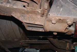
10 Once rear pivot bolt loosened, undo subframe mount and lower rear of subframe
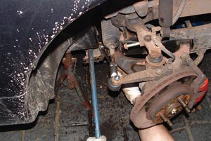
11 Subframe may need gentle levering to get it unstuck
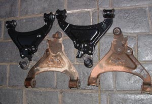
12 Removed lower arms both showing serious corrosion, new arms for comparison
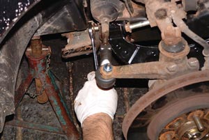
13 Refitting rear pivot bolt before raising subframe. Note disconnected damper bolt.
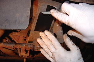
14 Use suitable weather proof tape to seal subframe front pivot bolt access holes
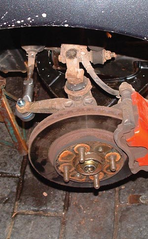
15 Complete ready for wheel replacement
The jack is lowered and in theory the subframe drops with it. It may be a little sticky and need some additional encouragement to drop with the aid of a lever, but once free it only needs a short drop to allow the rear lower arm pivot bolts to be removed. Here the value of previously loosening the bolts shows through, as trying to undo very tight bolts with a subframe loosely held by two front mountings and just resting on a jack at the rear, would be precarious.
Once the pivot bolts are removed it is a matter of removing the arm from the subframe and once again this may need the assistance of leverage with a couple of pry bars. When it’s out, clean the subframe up and slapping a bit of Waxoyl in the recesses is no bad thing for anti rust purposes and will aid fitting the new arm.
Fitting the new arm is a reversal of how the old one came out and hardly rocket science. The Waxoyl helps lubricate the refit, or if you don’t have any then some liquid soap on the bush ends helps slide them in place and to align the bolt holes for the pivot bolts.
With the bolts in place and wound almost fully in, the subframe can be jacked back up and the rear subframe bolts refitted and tightened to 45Nm, followed by the front bolts to a lower setting of 32Nm.
Next the lower arm is swung up to engage the ball joint pin with the hub. Take care to align the groove around the pin with the bolt hole in the hub, otherwise you will find it impossible to fit the locating bolt. Once in, the nut and bolt are tightened to 45Nm.
Next the anti roll bar is swung back up and connected to the bracket on the new arm and ideally the bolt should be fully tightened only when the car has weight on the wheel and the suspension. In the DIY scenario this is difficult and correct tightening is more important than ideal position to tighten it. Place the jack under the suspension arm and raise it until the car is just starting to lift off the axle stands. Now remove the wedge between the upper arm and bump stop and then tighten the anti roll bar bolt to 35Nm.
Whilst the suspension on that side is carrying the car’s weight the lower arm front pivot bolt can be tightened to the correct 85Nm. But unless you have a specific torque wrench that uses ring spanner ends you will only be able to get a standard socket and torque wrench onto the rear pivot bolt. With spanner only access you simply tighten as much as you can, bearing in mind the bolt could never come out.
Now the damper is refitted noting that the bolt is passed through the upper suspension arm from the rear pointing forward, and that the order of parts on the front side of the arm is; spacer, large flat washer, damper, large flat washer and nut. Early cars did have a problem in that the washer size was too small and so if the damper lower bushes degraded and allowed movement between the damper eye and bushes, the damper could easily pop off the mounting and hang free. There was a recall for this but some cars have slipped the net and when dampers are replaced sometimes wrong washer sizes are used. Also before the dampers are refitted there is much better access to insert a grease gun onto the upper suspension pivot grease nipples and it is well worth giving them a few pumps.
Repeat this process for the other side
Wheels can be refitted at this stage but it is very important not to forget to tape over the front pivot bolt access holes with a suitable weather resistant tape. The last job is to crawl back into the driver’s footwell, align the steering joint to the rack pinion, and slide the joint back onto the pinion before refitting the bolt and tightening to 22Nm.
The car can be lowered to the ground and then the wheel nuts finally tightened to the correct torque, which is 70Nm.
Overall the job is not as difficult as it may seem, although it has its fiddly aspects. The replacement arms should have a life equal to the originals and this may be extended if desired by a better coat of paint before the arms are fitted. It is certainly a job that can be reasonably expected to affect a huge proportion of MGFs and in time TFs too, and incidentally if there is ever a need to replace just the lower ball joint, then my advice is not to mess around with drilling out the three rivets holding the ball joint in place, but go straight for a replacement arm, it is a much quicker and easier way to replace the ball joint.