MGF Head Gasket Failure Part 5
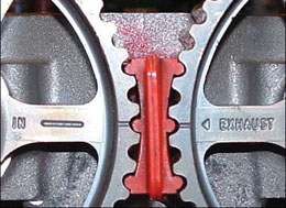
The general rebuild is essentially a reverse of the strip down sequence. Remember the hint to apply a drop of thread lock to the cam wheel bolts before refitting. Then you will need to align the cams and insert the cam locking tool to hold them in place. Whilst the cam-locking tool can be something you work without in FWD cars, which have better access, the MGF engine bay being so restrictive does require the cam-locking tool, and I really can’t see any advantage in messing about for the sake of a £5 tool.
Cam locking tool
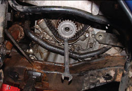
Shortcut to stopping cam belt from slipping
When it comes to fitting the (new) cambelt(s) there are a couple of small hints to ease the job. The first is that even if refitting the original (more flexible than new) belt you get the impression that the belt has shrunk, such is the apparent lack of length when you attempt to get it over the pulleys. The second possibilty is that because of this apparent lack of belt length you can easily fit it with a tooth out.
When looking at the toothed wheel for the belt on the crank there are two timing dots stamped into the front face of that toothed wheel. These marks are aligned with a cast-in line on the oil pump body and the idea is that the dots are positioned with one either side of the line. I now always move the crank back (anticlockwise as you look at the crank) half a tooth and now when the belt is fitted between the crank and exhaust camwheel the belt easily slots into engagement and when the slack is taken out the correct timing is achieved. Only half a tooth remember; no more or you will end up one tooth out the other way!
Another tip concerns the annoyance of the belt slipping around the crank toothed wheel because until the belt is tight it can easily jump around. The image shows how a suitable ring spanner can be slid into the space between the wheel and the lower edge of the casting belt guide and lightly holds the belt without risk of damage, yet stops any unwanted jumping as you fit the belt over the exhaust cam pulley, inlet pulley and around the tensioner and water pump. As the ring end of the tool is smooth there are no sharp edges to damage the belt, just gently locate it.
Tensioner setting and tightening is a vital aspect and here the simpler one is the later (1999 on) auto tensioner type as there is a built in spring guide and groove to show correct tension. This works simply by engaging an Allen key in the visible adjuster hexagon hole and turning clockwise whilst using a mirror to look at the tension probe move until the pointer end is between the Vee marks if the tensioner bracket. The bolts are tightened and the engine turned over twice and alignment and tension rechecked.
The manual tensioner follows the same general procedure, but tensioning is officially checked using a specific gauge. As most don’t have this, a guide is to be able to hold the ends of the belt between the cam and crank pulley wheels and to be able to turn it through nearly 90 degrees. Note if a belt is tensioned too tight you’ll hear it whining when the engine is running and if this occurs slacken it off a touch. Remember the tip about renewing the tensioner, especially the manual types that seem to have a shorter life compared to the auto types.
The exhaust manifold gasket may seem to fit either way around but actually it is handed with the clue in the end mounting hole. The end with a cut out goes next to the coolant outlet elbow. At this time with the studs replaced a little effort may be needed to lift and position the manifold over the studs if the down pipe remains connected. The now thoroughly cleaned and therefore easy to wind on nuts will pay you back for the effort of cleaning them!
Whilst remaining reassembly is quite straight forward, even to someone not that familiar with the K series engine, one area demands detailed attention. This concerns the correct sequence for the coolant fill and bleed, something that many people do not give enough detailed attention to, and this includes some professionals. The complex nature of the cooling system demands that air is expelled out of the system, otherwise air locks can quite easily have a serious impact on coolant flow and cause repeat overheating problems and bringing about yet another head gasket failure, not something you want to experience again so quickly!
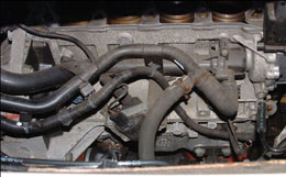
View of the main coolant pipes looking in to the engine bay from the boot. Bypass is the smaller bore pipe
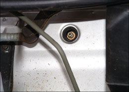
Heater bleed point under the centre of the windscreen panel
Before refilling, check the underfloor coolant pipes and especially the radiator lower section as seen through the air intake under the number plate for excessive corrosion. MGF radiators corrode far too fast and many owners are surprised by the fragile state in which these vital components are often found. A similar situation applies to water pumps and now is the time to replace these items, if necessary before refilling the cooling system. The later TFs incidentally have radiators fabricated in different materials and that seems to reduce corrosion problems.
The routine for refillling is first to note the capacity of the whole system, just over 10 litres, made up in a 50/50 mix of water and antifreeze. Be very careful to note which specific antifreeze your engine had before, as mixing the two types in not permitted. Up to around 2000 the traditional green/blue antifreeze with ethylene glycol was used, and from that time the newer pink/orange OAT (Organic Acid Technology) type is used. A label around the expansion tank lid should confirm which type was used. A dry fill uses just over 10 litres, but if refilling after a HGF repair a lower volume will probably be needed depending on how far the cooling system was drained.
In any case it is best to mix up enough coolant and water to fill the system so a continuous fill can be done, but before pouring into the expansion tank open the bonnet and remove the flimsy black plastic sheet that is fitted over the bulkhead area behind the spare wheel. There are four points of fixing for this, an upper plastic nut on the right side and a plastic scrivet on the left. The two lower points of attaching are usually of the plastic slide over two pegs type. Once removed not only can you see the two coolant hoses that pass coolant between the engine and radiator and back again, but also the small brake caliper type of bleed nipple sticking through the bulkhead from the passenger compartment tucked under the centre of the windscreen panel. This is the heater bleed point and it is undone, along with the heater knob turned to ‘hot’. Then there is the radiator bleed point, a larger plastic plug/bolt seen through a cut out in the bonnet-locking panel, next to the left hand headlamp. Do check the thread on this as it is plastic and easily damaged by over zealous treatment, and replace if need be before the coolant refill.
Ideally get an assistant to pour coolant into the header tank and when a steady stream of fresh coolant is coming out of the radiator bleed point replace the plug and tighten with just a final ‘nip’, remembering it is only plastic. Continue the pour and when there is a steady stream of coolant coming out of the heater bleed then tighten the bleed nipple. Continue the pour until the coolant level is to the correct mark, that is usually a smidgen above the moulded centre crease join in the expansion tank, depending on model, but they are all marked.
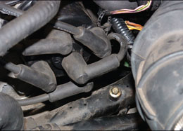
Cooling system bleed on coolant return pipe over clutch housing – the bolt
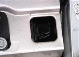
Radiator bleed point next to the left headlamp
Before replacing the expansion tank cap, do a check of the underside of the cap for a faulty valve. When the cap’s inverted you will seet a centre hole in the plastic cap moulding and inside this there is a brass plate with a rivet which should sit right in the middle of the hole so it is at the true centre of the cap. It’s not uncommon to see this rivet offset and when it is, the correct cooling system operating pressure will not be achieved and coolant will often blow out of the system. Replacement caps are available off the shelf at virtually any motor shop or from MGOC Spares for little money.
Now it’s time to fire up the engine and it is best to hold rpms at a steady 1500 to 1800 rpm during this warm up phase, whilst watching the temperature gauge and feeling hoses. If the coolant level in the expansion tank drops suddenly soon after the engine is started, top the level up and continue. If the level drops but is still visible in the tank then continue with the warm up cycle. It will help here if you have an assistant sitting in the car on the throttle and watching the gauge while you attend to engine bay and feel the smaller bore bypass pipe that runs around the rear of the engine next to the bigger bore rad return pipe and you can feel the coolant flow and water temp rise. It soon becomes too hot to hold and by this time there should be the first signs of heat coming from the heater (fan on of course).
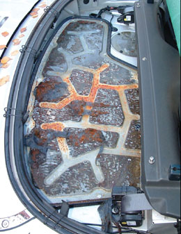
Rain water can soak the insulation and cause this!
If the hoses quickly balloon and become very hard with internal pressure then this is a sign of an airlock and poor coolant flow, it is usually accompanied by a rapid rise of the temp gauge and early cooling fan operation. Switch off allow to cool and re-bleed. Often raising the front of the car helps to move difficult airlocks.
The heater output should soon climb to the normal good heat output and at this time you can switch the fan off as you now want the rest of the cooling system to come into full operation. If it doesn’t then it is air locked so re-bleed again. This final phase does take quite some time to get going with those 10 litres of coolant to gradually feed through and heat.
During this main phase a watchful eye needs to be kept on the temp gauge and it should quickly rise to the normal position, usually a notch under the half way line, and stay there for perhaps 20 minutes with the engine running at 1500 to 2000rpm before heat arrives at the radiator or return coolant rail. If you see any sudden gauge fluctuations then this indicates an air lock and need to bleed again.
When the system is working normally with the return pipe at the back of the engine hot and the temp gauge still showing normal, fan operation should follow soon after. (Not the engine bay cooling fan in the right side body vent but the front radiator fan.) The fan should remain on for perhaps three to five minutes and cut out. If this occurs then it is the desired result and time to recheck the coolant level before going for a couple of mile’s drive to settle things, keeping the heater on as if there is any developing/moving airlock then the heater will start to blow cold as a clear warning. Normally at this stage things are fine so on return let the car settle for a few minutes before doing a final fluid level check.
Note specifically that a cooling down time is needed when looking to top up or re-bleed the cooling system as an air locked system has a high pressure build up quite quickly and when the expansion tank cap is released there will be an ‘old faithful’ geyser of hot water to injure you!
If the system doesn’t bleed properly and the warm up cycle still shows an airlock then after a cooling period go to the coolant return pipe over the gearbox clutch housing and look for what appears to be an 8mm headed bolt into the pipe. This is the third bleed point and used when bleeding the system is difficult and fails to work with the two front positioned bleed points. Repeat the same bleed sequence as before with the rad, then heater and now add the return rail bleed to ensure air is out of the system.
Note FWD cars only have this single 8mm bleed point in this return rail and I often find that with all cars, initially opening this bleed point when starting the fill and waiting for coolant to stream helps the overall bleed process, although this is not in line with the ‘official’ procedure.
Make a note to recheck coolant level again the following day when the engine has had a full overnight period of cool down and by then often small additional airlocks will have moved and the level may have dropped slightly. Repeat this daily check for a period of a week or so, but once the level is achieved then it should remain constant.
When you are happy that the cooling system is functioning properly it is time to reassemble the car, which should be simple and need no further comment. However, I mentioned earlier the very tight space for three of the eleven bolts holding the engine bay cover in place when the car has rear speakers fitted. Those you have to persist and fiddle with, but the bigger problem comes with the insulation which is often a very tight fit, and getting this back under the speaker box a real pain. However, if you spray the top smooth surface of the insulation that slides under the speaker box with WD40 or similar it slides under a treat.
I also suggested that cheap oil be used initially as a means to flush any coolant and other deposits out of the engine. Adding this and running the engine around the block plus the 20 to 30 minutes of other running whilst bleeding and verifying the cooling system should be enough to remove most deposits and time now to drain this oil whilst it is stinking hot (you can leave it in longer if desired). Before draining the oil you may wish to use a flushing agent as per the instructions on the can. Note that when adding a flushing agent it turns oil into water, and when you remove the sump drain plug it will gush out like water but often hotter than boiling water, so take extreme car and protect your skin from scalding splashes. It does however have a very good flushing effect. Adding fresh oil you normally use a new filter and should see the job done apart from a wash of the car and then a daily fluid level check for at least a week to ensure no leaks go unnoticed.
Look at the cost of your parts and it will come to only a fraction of the professional cost of repair, assuming no special additional headwork is needed. Now reflect with the satisfaction of successfully completing this job, saving you not just money, but in the case of an older MGF probably keeping the car on the road, and done properly there will be many miles left in the engine.
The merits of the Land Rover MLS gasket was discussed some issues ago, but to reinforce the belief in the effect of this design a new MLS gasket of very similar design to the Land Rover one has been produced by BG Automotive, part of the long standing British Gaskets Group. See Hot Lines in this issue for this and other great offers for the K series engines.