MGF Heater Air Intake Modification
One of the enduring faults of almost every soft-top car is not being able to keep all of the weather out, specifically rain. The reality is that this is almost impossible and only the most expensively engineered soft-tops approach that Holy Grail position of being really watertight. For the mainstream soft-top cars the reality is that rainwater entry into the passenger compartment will occasionally occur in specific weather conditions. However, with the MGF and TF there are some examples that go beyond the ‘leak occasionally in exceptional conditions’ to a ‘leak almost every time it rains’ scenario.
This wholly unacceptable position can in most cases be addressed and often the causes will be one of several common entry points. One aspect has often been wet passenger (left) side footwell carpets and frequently the expected point of water entry is through the ‘Cheaters’ (the triangular door mirror mountings) there are usually a few dribbles visible on the inside door trim after rainfall when the car has been parked. Whilst the water through the cheater can wet the carpet, very wet carpet and the sound proofing underlay is often a sign of seal failure between the heater air intake plastic chamber and the bulkhead.
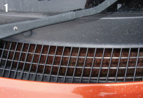
Typical rusty rain deflector under plastic windscreen grille
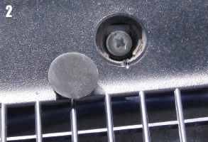
Removed screw cap and cross headed screw of which there are six to undo and extract
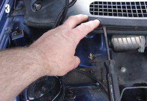
Rear screws removed and screwdriver showing a gentle lift of one of the six front clips
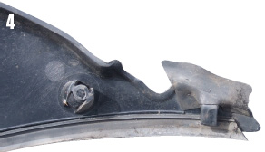
One end of the plastic windscreen air intake grille showing the ‘clip’ that hooks under the glass…
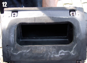
Early MGFs were more prone to leakage in this area and this was due to a weakness in the seal design that’s glued to the base of the plastic chamber. The seals were uprated from around 1998 and whilst this significantly reduced the problem it did not always provide a complete solution. The image showing the seal on the base of the chamber removed from my 2001 car shows clear water staining and indicates that whilst the car was dry, water was still able to penetrate and in time this would have become a problem. Incidentally the damage seen to the lower left of the seal was done removing the chamber.
Another common related problem with this design of plastic chamber is the steel rain deflector rivetted and clipped to the top opening of the chamber. This item stops rain coming straight through the plastic grille at the base of the screen on the passenger side and straight down the air intake towards the heater, which of course would be straight into the passenger foot well area. The deflector does a quite reasonable job of deflecting the rain and diverting it to collect inside the chamber near to the drain holes where it escapes harmlessly.
Quite why it was made from poorly protected steel has always seemed odd as the painted steel deflector will over time corrode and become an eyesore that always seems to be peeking through the plastic grille and trying to attract your attention! As removal of this chamber in one piece suitable for refitting is, as we shall see, a real pain, the best solution to the rust is to remove the plastic moulding at the base of the screen, that will allow access to around 80% of the plate for cleaning and repainting, but will at least include all the visible parts. Image 5 shows this more clearly and for those wondering what the purpose of the spring clip is, it is to stop the plate vibrating. As an aside, I found that by simply spraying a light application of aerosol spray grease through the plastic grille helped delay the onset of serious corrosion.
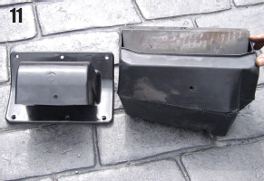
Whilst my car was not suffering water ingress and had a bearably presentable rain deflector, there was still the desire to improve things. This was mainly driven by the simple fact, probably little known, that from mid 2003 (VIN 3D612109) the TF benefited from a completely new air intake moulding that was smaller, neater, better secured and adopted an almost stupidly simple shape to prevent rain entry. The image of the two types illustrates this perfectly (image11).
…which is seen better from this angle
Air intake aperture showing rain deflector that has not rusted as badly as many due to occasional spraying as mentioned in text
Exposed underside of the air intake – looking from the footwell and showing one of the two fixing that have to be removed
Quarter drive tools small enough to be more convenient to remove this front fixing
Original air chamber removed showing how dirt collects
Dissected chamber to allow removal without major additional component strip down
Removal of the old and fitting the new is on paper (or in Workshop manual speak) simple, but isn’t so in practice. The main difficulty is the removal of the original chamber; as it quite literally fills the space available and is an item fitted early in the car’s original build with many items built around it later, such as the braking system, which would have to be removed for removal of the chamber in an undamaged form!
New and old air chambers
Underside of original chamber showing water staining on seal indicating leakage was not far off
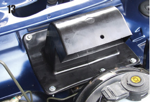
New air duct fitted, note hole in front is for the plastic cover trim as seen in image 15
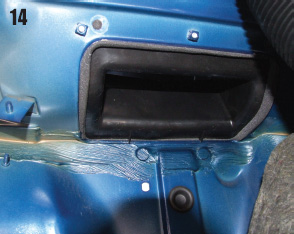
Underside of new duct in fitted position
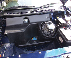
Finished with original plastic cover in position
In my case I did not intent to reuse the chamber and so decided to sacrifice it to avoid the complex removal and refit of the brake parts. It is important to note that the replacement TF part is something that can be fitted with all the other parts left in place. Initially the bonnet is opened and the rear plastic cover is removed, plus for convenience the spare wheel and tools. The wiper arms/blades have to be removed with each held by a single 13mm nut. Note that the domed nut is for the driver’s (right) arm and the normal nut is hidden under the removable trim cover of the other arm. The arms sit on a heavy tapered spline and may need a little coaxing to remove. Note the position the wipers sit in to enable them to be refitted in the same place and so avoid the need to adjust them after they are refitted.
The plastic grille at the base of the screen now has to be removed and here there are six screws under plastic trim covers nearest the windscreen glass. The covers are levered out (carefully) from the small indent at the six o’clock position, cup your hand over them as some will spring out with the energy of a world championship tiddly wink never to be seen again if you don’t! Once removed put the screws and caps somewhere safe (image 2).
Now move to the seal at the front edge of this plastic grille and fold the top edge forwards to reveal the heads of a further six plastic trim clips. Ease the head upwards and out very gently, ideally with a trim clip removing tool, and store the clips with the other screws and caps. The seal itself is usually bonded in a couple of sections to the trim, but if not it can be placed aside for cleaning before refitting later (image 3).
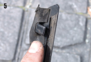
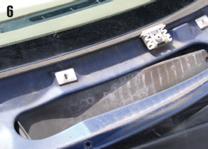
The plastic grille is now theoretically free to lift out and here is when most people break the ends. There is a moulded tongue at each thin end of the grille that clips under the edge of the glass (image 4 & 5) and you have to take great care to fiddle the trim to disengage this. These are originally fitted before the bonnet is fitted and it is the hinges that restrict the simple removal of this trim, although with care this is possible.
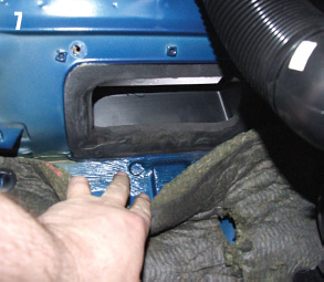
Removal of the chamber is next, starting inside the passenger foot well. Firstly remove the glove box for better access behind and then remove the heater air duct that connects the underside of the soon to be removed chamber to the heater unit (image 7). This is a simple removal of a single M10 nut and easing the duct off, just as was described recently in the heater resister replacement feature in the April 2008 issue. Interestingly there was no nut fitted to my car and with no signs of compression on the plastic it seems that there never was one. Once removed the compressed seal at the base of the chamber can be seen along with the two rear 10mm headed self-tapping bolts that hold the chamber to the car were removed.
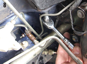
Work now moved outside and the chambers two front fixing bolts, one of which nearest the centre of the car (image 8) is reasonably accessible through the maize of hydraulic pipes, but the last one is buried behind the servo and under the extended shape of the chamber. Fortunately there is an access hole in the subframe that allows a long extension with a ‘wobble’ end for the 10mm socket to be inserted from underneath the car, once the car was raised and supported on suitable axle stands.
With all four fixings out the chamber is free to move within its limited free space. For those whose cars leak water past this seal it is not adequate room to replace the seal, although the universal ‘fix all’ silicone sealant could be tried, if this was the only problem.
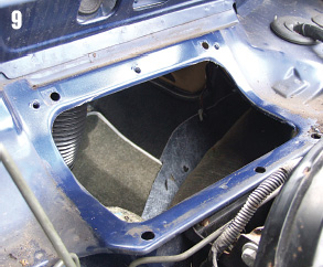
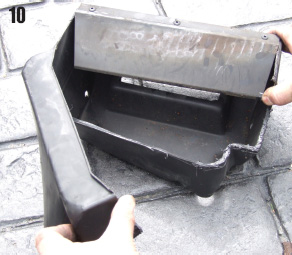
The shape of the chamber prevented simple removal but it was clear that if the chamber was cut it could then be compressed, rotated and lifted out. Having an air saw saved much effort as the plastic used for the chamber is quite thick, and once cut to allow the front upper half to be folded open, allowing the whole chamber to be rotated upwards, clear of the servo and out. The space revealed was surprisingly large (images 9 & 10).
Years of inaccessibility means there is plenty of dirt and here is a golden opportunity to have a good clean before the new duct was fitted. There was also some excess seam sealer causing lumps where the seal fits, so these were trimmed flush to aid the life and efficiency of the new seal.
Fitting the new TF air intake funnel is by comparison to the removal of the original chamber, a doddle. There are some differences beyond the obvious visual ones and the most important one is the use of six fixings instead of four, so the clamping load is better spread, but four of these six fixing holes are in different positions. Immediate thoughts of drilling new holes were unfounded on this 2001 car as the required holes were already present, including three captive nuts and this may also be the case for earlier cars too.
The three rear holes are in different positions to the original chamber two rear fixings, but here the car already has three captive nuts in the body and so all that is needed here are three M6 bolts of approx 20mm length and three flat washers of a size adequate to cover the holes in the new air intake (Image 9 &14). The front holes use the two original holes from the original chamber and the third too was already present, and again all that was needed were three new bolts, this time with three nuts as well as three pairs of washers. With so much space fitting the rear bolts is really simple, but the fronts remain a little restricted by the proximity of the servo, brake pipes and the flange of the leading edge of the bulkhead. Be careful not to over tighten these fixing, as is easily possible, that will distort the plastic base of the air intake.
Time now to refit the trim and wipers and here I simply make the point to take the same care with refitting the plastic grille as was needed when removing it. Also do not screw in the rear fixing screws too tight, as this will break the plastic clips. It is also an idea to dribble some water around the new intake in a manner that imitates rain draining off the screen and down around the intake, to check for any leaks. When satisfied the interior parts are refitted.
The end result (images 13 and 14 ) is in my mind neater and simply a better design and the wonder is that it was not fitted earlier. In testing I did note that there seemed a little more air noise when the fan was on full power, but that was from outside, inside was no noisier.

The later TF air intake is found under MG part number JKA000120 and priced (May 2008) at £36.82 plus vat and should be available through normal MG spares outlets.