Performance without Consumption – MG ZS – (part 3)
Engine management – Part 3
One area very seriously delayed this project and it was the engine management system. As the base systems of both the ZS and the ZT 1.8T are the same family of MEMS3 and sit in the same ECU box with the same two external connectors, it was hoped that I could simply plug the Turbo ECU into the wiring with a couple of added wires and drive off. What we didn’t know about initially was the huge number of differences that there are between these systems and the depth of complication there is with the interfaced ZT engine management and security system.
As we looked deeper into the issues, hurdle after hurdle arose all of which needed to be overcome, but the attraction of factory mapping for this engine, with perhaps a later tweak to raise power beyond the standard 160ps level kept us pursing this course. Some of these concerns I will mention and how they were overcome, but still we changed tack later on.
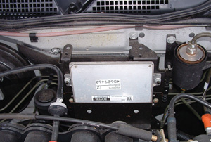
Original ZS 120 MEMS3 ECU
The first point is the much higher level of security that applies to the 75/ZT models and is titled EWS3, a BMW based system. This sees several ECUs (Electronic Control Units) inexorably linked together and needing to have a constant connection and exchange of security codes otherwise they shut down. These are all once only coded items so offer no later reprogramming as can be used with other K series MEMS pre 2004. This means the only really viable route is to use a set of matched ECUs from a single 75/ZT donor car.
However, starting with a set of matched ZT MEMS3 ECU, EWS3 ECU and one key allowed our personal electronics wizard to start to slim down the system by first deciphering the 75/ZT key, then creating a clone that was fitted inside the EWS3 ECU to provide the continuous rolling code and keep the system live all the time the ignition was on. The MEMS ECU being already coded to the EWS3 then needed only to have the correct wiring connection. By borrowing a ZT 1.8T model and fitting the modified EWS3 and MEMS ECU, plus disabling the donor car’s key and transponder, the car ran perfectly. This process is much easier said than done.
The next hurdle was the fact that the 75/ZT set up uses a digital crank position signal whilst all other MEMS systems use analogue. Converting the signal is quite possible and for the electronics wizard, relatively simple, aside from the complications of needing to know how MEMS interprets the digital signal. Interestingly other MEMS systems actually convert the analogue signal within the ECU to a digital format so a spare MEMS 1.9 ECU became a signal converter with a jumper to alter the position the signal was read from the reluctor tooth on the flywheel.
Whilst the format of the crank signal was being addressed another conflicting issue surrounding the timing of the signal was being dealt with. The bottom line is that the pattern of the flywheel reluctor is different on the 75/ZT to all other post 1995 MEMS systems. In simple terms the system is a 36 – 4, which is a wheel that has teeth at 10 degree intervals and so for a full circle there would be 36, but has 4 missing teeth at varying locations to allow the MEMS ECU to know the exact engine position at all times and which cylinder is where in its cycle. All recent MEMS systems have operated with the same 36 – 4 pattern, except for the 1.8 litre 75 and ZT models, which have two of the missing teeth in different positions to the other MEMS systems. This may only be a small difference, but it is a critical one.
Yet another difference and added complication is that the 75/ZT uses a Getrag gearbox and different flywheel that has no relationship to the PG1 gearbox pattern flywheel. Differences continue with the mounting position of the crank sensor being in a different location in the gearbox case rather than the common in the block position of the other K series engines, but at least the turbo engine block retains the sensor mounting position in the rear of the block.
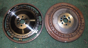
Flywheels, standard PG1 on right, lightened steel one with one off reluctor pattern on left
Unfortunately with the Turbo ECU demanding a different reluctor pattern, simply using the original ZS flywheel, which has the reluctor pattern machined in the back, was not possible, so taking information from several Rover documents the 75/ZT reluctor pattern was transferred on paper to be applied to a PG1 flywheel, and then a special one off lightened steel flywheel with this different pattern was commissioned. It took quite a while for this to be made and when it arrived it was fitted to the engine and the slave MEMS 1.9 ECU was connected between the Turbo MEMS3 and crank sensor to convert the signal.
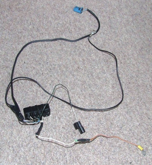
To use the analogue ZS crank position sensor the signal has to be converted to a digital format and here is the small addition loom that connects the sensor to the MEMS3 ECU
At this point having already had to overcome so many hurdles an immediate engine start was somehow not expected, and it didn’t! We knew the ECU and the modified EWS3 worked as we had proven on another ZT 1.8T when it ran perfectly. So the next step was for our electronic whiz to connect his laptop with an oscilloscope program to compare the signal patterns from a working ZT 1.8T against the signals from the ZS. This showed the same pattern, so the reluctor pattern was correct, but the signal was very weak. The ZS signal was based on a 5 volt sensor input but the ZT was running a 13 volt one (i.e. full electrical system power level). Upping the ZS signal to emulate a 12v level saw the ZS start on the button, but not with the same smooth sweet running as the ZT next to it. Remember that we knew the engine was in fine fettle as we ran it for a while in non-turbo mode.
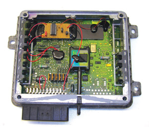
Having first been been converted by a modified MEMS1.9 ECU
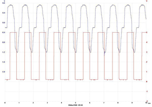
The wave form of the analogue crank sensor signal is the upper trace and the converted digital signal is the lower one.
With such a Heath Robinson set up there could be several reasons for the rough running, but after so many months of brick walls, just hearing the engine running was a joy. Nevertheless the process of finding out which fault was causing the poor running had to be found and corrected.
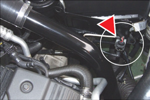
The turbo wastegate is set at a low 6psi blow off pressure and higher boost levels are controlled via the ECU controlling this small boost valve shown here
Fuel pressure and supply was one difference between ZS and 75/ZT, the latter having a different fuel supply system where all the regulation is done in the tank and a single feed goes to the engine. ZS uses the traditional pumped supply to the engine and a regulator at the engine maintains the correct fuel pressure and returns the excess to the tank. Initially the fuel pressure was wrong and lower than the standard 3.5bar used on the 75/ZT, but when correctly reset after fitting an FSE pressure regulator there was no real difference.
What was difficult to fully understand is that whilst it was running rough most of the time and not able to idle without some throttle assistance, some of the time it was really quite smooth and looking back that did lead us astray by making us think that there was a subordinate problem rather than a more basic one.
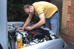
Owner and car in perfect harmony!
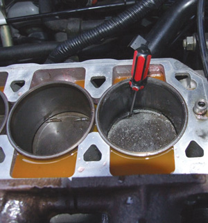
Severely damaged piston and liner following problems setting up the engine management (see text). Here the head has just been removed and the screwdriver blade fits between the back of the piston ring and piston!
To cut a rather long story short the testing process ended up with the oscilloscope again to record crank and cam signals on the same screen. This involved getting another ZT 1.8s engine running at a specific rpm and then trying to get the ZS to run at exactly the same rpm, not easy but important to try and get accurate information to compare. We managed to get some readings that were close enough to get a picture of what was happening and then look for differences.
What we found was that the reluctor pattern was correct, but when the cam signal was viewed against the crank signal there was a position difference between them. In simple terms knowing that the cam timing was correct for both engines it could be used as a basic timing base line and this showed that the ZS crank signal was between 20 and 30 degrees advanced. Double checking all the available information and images of the special flywheel didn’t show any variation to the way it had been machined, so the conclusion was that the base information from which the positioning of the reluctor was done was wrong.
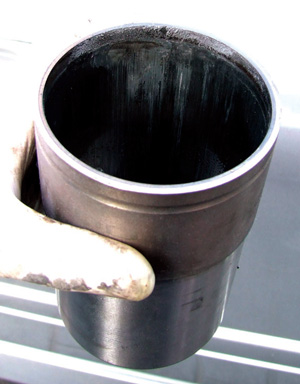
Heavily scored liner
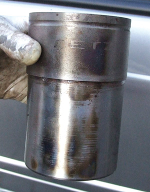
Liner showing serious overheating
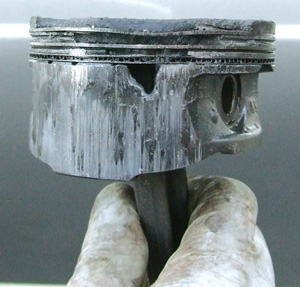
Heavily damaged piston
With this in mind it is unfortunate to report that during one of the subsequent tests the engine dropped onto three cylinders and started to spit oil from the breather and dipstick tube, plus out of the exhaust. A quick compression test showed very good even pressures on 1, 2 and 3, but zero on number four. The combination of serious crankcase compression and nothing in number 4 pot indicated piston failure, but how bad demanded that the head be lifted. The images tell the sad story of a toasted liner and in simple terms a vapourised piston, which was more than enough verification that timing was seriously advanced. At this time aside from the need to source a new liner and piston the decision to continue to follow this route to keep factory mapping was dropped since a new one-off flywheel would be far too long in the making, so the back up route of using an Emerald K3 engine management system was pursued, a system we have running on an MGF and have very positive experience of with other cars.
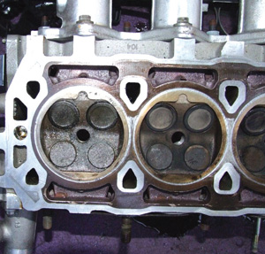
The small vapourised particles of piston covering the combustion chamber and valves in the head like a crust. Fortunately easily removed
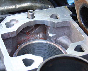
Before fitting the new liner a small notch was ground into the buttress next to number 4 liner with the intention that it helps coolant flow. The effect and results of this are difficult to assess
The engine was sick with the damage centred on number four cylinder and some of the vapourised piston coating the combustion chamber and valves in the head. Fortunately the coating was like carbon deposits and easily cleaned off, but there was no future for the piston and liner and so the search was on to find new ones. A liner was still on the Xpart shelves, but the pistons were unavailable; however Dad was able to find one and have Ivor Searle remove the damaged piston, and fit the new piston to the unaffected rod.
Interestingly other K series engines that have suffered piston and liner problems are frequently affected in number four and the intimation is that there may be insufficient cooling around this liner. It is also apparent that there are buttresses in the block that butt up to number 1 and 4 liners and as a trial I put a notch in the buttress next to number 4 liner to see if this helps improve coolant flow around this area. Whether it does or not I can’t be certain, but it was a case of do it now whilst the engine was dismantled or not at all. Suffice to say with many road miles and considerable full throttle rolling road stress later the engine hasn’t seen any repeat problems.
Matt Parker