Revival of an Old Friend – Part 5 Fuel Injection continued…
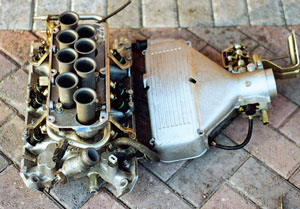
Losing 27mm from the Hot Wire injection system is quite a tight call when the clearances for all the various parts are considered. The injection manifold consists of three separate pieces, a base manifold, intermediate ram stack housing and a top plenum cover that also houses the throttle. It was now a case to decide exactly where metal should be removed from.
Lucas Hot Wire injection manifold system with plenum removed
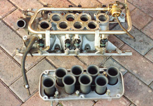
Hot Wire base manifold and removed ram stack housing
The ram stack housing was clearly the favourite as once the ram pipes were removed (as they have to be) there were two flat machined surfaces, top and bottom, meaning that was easy to set up for machining. Unfortunately not all the 27mm could be taken from this casting, with some 15mm coming from the base, 4mm from the top face, leaving 8mm to be found and that came from the underside of the plenum casting where it joins the ram stack housing. These were the maximums available with the various bosses and fixings present. The curved top of the plenum change did add to the difficulties in setting up for machining but not too many. Those with Land Rover familiarity will point to the post 1994 square top injection plenum for an easier machining route, but unfortunately this plenum doesn’t fit under the MGB bonnet.
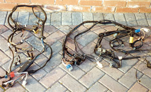
Hot Wire wiring loom on right, simpler Airflow Meter system on left
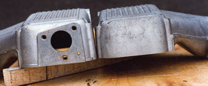
Lowered plenum on right showing effect of 8mm skimming. Left standard plenum shows three idle control valve housing bolts mentioned in text
Before any machining was done the steel ram pipes had to be removed from the alloy ram housing, and they are glued in quite effectively. In addition knowing that 15mm was being removed from this lower face, means the two location dowel holes that align the ram housing to the dowels in the manifold would be machined away. Simplicity applied, and these holes were simply drilled another 15mm deeper so they would still be present to the correct depth and position after machining.
The fitted ram pipe positions shows the inner four sit higher than the pairs at either end, which is to ensure the inlet tract lengths remain equal. It will be seen that they sit on top of a machined collar. It was clear that the depth of this collar from the mounting face is shorter for the outer pairs and only 7mm. Therefore the 15mm machining would go 8mm beyond this collar, and so this has to be removed from the ram pipes before refitting, but there is more to consider here which I will come to in a moment.
The ram pipes needed to be trimmed to keep the same clearance between their tops and the underside of the plenum chamber when fitted. The effective lowering of the plenum, from the machining of the upper face of the ram stack housing and the underside of plenum was 12mm, so this is the base reduction off the bottom of the ram pipes, but only for the four inner ram pipes as the outer ones need another 8mm to take account of the lower machining removing their original seating position, so the outer four ram pipes were shortened by a total of 20mm. Keeping the original clearance for airflow purposes may not be needed to be this exact, but the principle of what worked before should work again applied and experimentation with clearance requirements is a job for another day.
Trimming the rams squarely is important to getting a neat seating. Note there is no need to create a new seat for the outer pairs as the manifold base will do this for you and a little thread lock when inserting the shortened ram pipes back into their housing helps to fix them. The overall length of the inlet tract is now a few mm shorter, which has a very small impact on the torque and power characteristics of the engine, indeed the change of injection system and use of RV8 exhaust manifolds has provided a quite obvious increase in performance so the issue will have to remain hypothetical. There are a couple of additional modifications that need to be mentioned. Firstly the mounting bolts for the ram casting to manifold and the plenum for ram casting are all too long and also need shortening by the same amount as the overall lowering, or better still get new ones of the right lengths. Next the original water heating adapter casting originally bolted to the underside of the throttle housing needs its four mounting bolt holes plugged as they go all the way through into the inlet air tract and should you forget to do this (as I did, initially) you will wonder why the engine is running so badly and noisily until the penny drops.
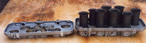
Machined ram stank housing on left showing the main reduction in height and rams removed. Standard ram assembly on right
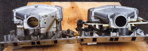
Fully lowered inlet assembly, right, next to a standard height one
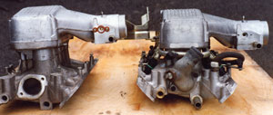
Comparison of the fully lowered inlet assembly, right, against the standard on the left viewed end on
Next the idle control valve housing on the rear of the plenum chamber is secured by three small bolts. Removing 8mm from the base of the plenum cuts slightly into the thread for the lower mounting hole. Before refitting I bolted the plenum to the ram casting then ran a tap through the partially machined lower hole. Whilst the thread now sits 75/25% between plenum and ram stack housing this provided more than enough purchase for the small fixing bolt and light torque used when finally fitting the idle control valve housing. Alternative solutions could also apply here with a little extra work, but I chose to start with this method and then review once the engine was running, but as there has not been any issues it remains in this format.
The only additional changes directly related to the change of manifolding revolved around different water hose connections. Previously with the Federal injection system a modified MGB heater valve was attached to a rigid outlet pipe adapter off the back of the manifold that conveniently controlled water flow into the heater. This time I took the opportunity to look at getting more coolant flow through the heater using the injection manifolds bigger bore heater hose connections and steel pipes, along with a much higher flowing control valve. This was to make the heater less of a joke.
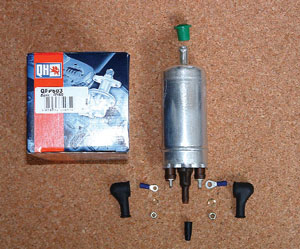
Replacement EFi fuel pump
Wiring involved changing from the previous Airflow Meter system harness to a more complex Hot Wire one, still a stand alone harness to make retro fitting to any other car simple, but there are several specific details that have to be checked and corrected if need be. The tune resistor is one of these system oddities and essentially this triggers the ECU to run in a specific mode, cat or non cat being the main difference, then there is another resistor function to tell the ECU whether the car has a manual or automatic gearbox. Not difficult aspects to deal with but a detail fiddle.
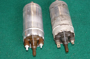
New (left) and old (right) fuel pump. Note the only difference is the electrical connections moving from spade to screw on
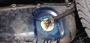
Retaining an RV8 fuel tank from a damaged car many years before proved invaluable when the original 1985 modified MGB tank suffered continued fuel pick up problems. The sender/fuel feed is a modified MGB one
I also mentioned earlier the inbuilt speed limiter that applies to all standard Land Rover cars with the Hot Wire injected V8 to cater for the low S speed rating of the tyres of the period. My ECU benefited from a remapped EPROM that is easily replaced as it sits in a specific saddle that allows simple removal and fitting of remapped chips. Many 14CUX have this set up but not all. The speed limiter actually works from road speed that is sent from a pulse generator within the speedo cable or instead of it in the case of Land Rovers with electronic speedos. If there is no road speed data then the speed limiter won’t apply, but in addition the cars smooth running in very slow moving traffic may be upset as the engine management doesn’t know when the vehicle is stationary to invoke idle speed control.
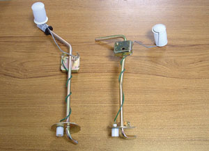
New rubber bumper MGB sender/fuel feed on left and standard RV8 sender/fuel feed on right
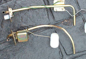
Standard RV8 sender/fuel feed upper and modified MGB unit below. RV8 sender has a reverse resistance sender so shows empty when full and vice versa. MGB sender modified to fit and work and the fuel pick up pipe carefully bent to sit at the same height as the RV8 one in the RV8 tank.
The existing injection modified fuel tank I had with the internal swirl pot and external Bosch injection fuel pump were retained, although the years of inactivity created initial running problems that manifested in a steadily noisier fuel pump and hesitancy with the engine. This did lead to one break down on an early Sunday morning ‘taking in the summer air’ drive out in the sticks. The car coasted to a halt outside a garden centre being guarded by a pair of loose Rottweilers who took an unhealthy interest in my presence, and seemed to be making unhealthy headway through the steel fencing in the five or so minutes that elapsed before the engine sprang back into life and I was gone.
After another twenty minutes the condition began to reappear, but by which time home was reached. Sod and his law as usual prevailed here in that this problem only became apparent after filling the tank. The noisy pump also raised the possibility of a fuel pump problem, and as this pump was 23 years old I decided to renew it, but this actually made no difference. Subsequently after replacing all flexible fuel hoses I pinned the problem to an internal fuel tank pick up issue and use of a spare RV8 fuel tank I collected a number of years ago has provided a solution.