A Twin Cam called Ratty – (Part 12)
When I first stripped Ratty down for restoration the shelves in my workshop were filled from top to bottom and end-to-end with rusty, oily and very dirty parts. Now I am approaching the end of the rebuild most of the parts have been restored and fitted to the car and the workshop looks rather bare. The heater and the dashboard complete with all its dials, switches and wiring were the last major items left and I was looking forward to returning these to the car.
|
 |
 |
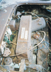
I tackled the heater first and knew it would be a challenge even before I started because it was very rusty with severe corrosion on all sides. This of course was the result of the rat infestation that filled the engine bay for so many years. If it had been the heater from any other MG it would have made sense to scrap it and buy a replacement. Alas this was not possible because as I have mentioned many times before in these articles nearly everything is special to the Twin Cam and that includes the heater. Although it is similar to the Smith’s heater used on other MGAs it is unusual because the fresh air inlet pipe is on the exhaust side of the engine bay. This is necessary because the carburettors on the twin cam block the route for the air inlet used on the push rod type MGs.
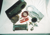
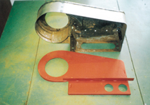
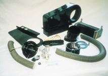
Prior to starting this part of the rebuild I had purchased a few replacement parts common to other heaters, such as new product labels, the spring clips that secure the assembly together and a water control valve. A cursory glance had told me that they would obviously need replacing and I knew they were readily available from most MG part suppliers. The strip down was straightforward and the photographs show that there are a surprising number of parts in a relatively simple device like the heater. I was relieved to find that although the case was very rusty everything else, the heater element, the fan and the motor were in good condition. I did a function check on the motor by connecting it to a car battery and found that it operated smoothly and quietly. It was clear at this point that if I could overcome the corrosion to the casing it would be possible to save the whole heater at minimal cost.
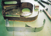
Corrosion of the heater shell was considerably worse across the top section and I made the decision to replace this whole piece with a new fabrication. Getting back to metalwork even for a small job like this was a reminder of the bigger task of restoring Ratty’s bodywork two years ago. It was enjoyable at the time but I was very glad I would not be facing that particular challenge again for a while! It was necessary to undo a number of spot welds to remove the corroded part and I then used the old part as a pattern to construct a replacement from new steel before carefully welding it in place.
 |
 |
 |
|
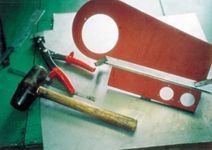
More metalwork was required to replace the flange around the heater which is used to secure it to the bulkhead. The original flange had all but disappeared due to corrosion but there was still enough in evidence to construct a reasonable copy and this I welded to the case. I used a rust remover product supplied by Hammerite to return the rest of the steel parts to bare metal before spraying each part with Bonda Primer as mentioned in earlier articles.
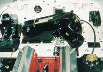
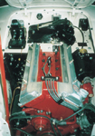
After spraying all the components with a final coat of black gloss there was another check I needed to do before assembling the heater. I wanted to ensure there were no leaks in the heating element to cause a problem once the car was up and running. I firstly flushed the element with hot water to remove any internal corrosion and accumulated debris. The second step was to conduct a pressure test by connecting the inlet pipe to the domestic water mains with a short hose and blocking the outlet to find any weakness in the heater core. No leaks were found and the heater was assembled and fitted to the bulkhead where it looked almost like new against the Old English White paint.
Now at last I could turn my attention to the dashboard. I had really been looking forward to this part of the rebuild which requires precision and attention to small details. The dashboard in any car should be aesthetically pleasing and designers spend huge amounts of time and effort trying to get it just right. Thinking about modern cars for a moment study someone who is looking at a new car for the first time. After a few minutes checking the outside most people move to a side window to gaze at the interior and especially the ‘dash’. What they are looking for is a stylish display of controls and instruments that are easy to understand and logically laid out. The dashboard displays information to the driver about speed, time, fuel and the health of the engine and houses many of the system controls and switches needed to pilot a car safely and efficiently. Looking at the dashboard of the MGA designed nearly fifty years ago, it is clear that the science of ergonomics was still in its infancy!
 |
 |
 |
Poor design is evident for example in the switches that control the wipers, the starter motor and the lights. These are activated by a pulling action, which is unnatural and clumsy. The wiper switch, interior light switch and the fuel gauge are inconveniently placed in front of the passenger seat which making them difficult to access. From a safety point of view there are many hard protrusions on the dashboard just waiting to injure you in the event of even a low speed shunt. It would be pointless to continue with this exercise, the car was designed in a different lifetime and the world has moved on.
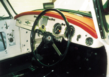
Having pointed out the faults of the MGA dashboard I still find it very pleasing to look at especially in the original colour scheme found on Ratty. When I acquired the car I hardly noticed that the dashboard was faced with vinyl and not painted the same colour as the bodywork. I have since discovered that it was only soft-top cars that were finished in this way. Early MGA coupes, painted in Old English White were supplied with an off-white coloured vinyl on the dash but I was not convinced that I would like this colour combination. Now the dash is finished I must say I think it is really effective but I am getting ahead of myself.
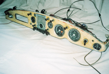
One of the best pieces of advice to anyone stripping a car for restoration is to remove the dashboard with all the instruments, switches and wiring in place. It is wise to not disconnect any of the wiring but simply cut it where necessary to enable the whole assembly to be taken out as one piece. This also applies to the control cables and anything else connected to the dashboard. It means you are presented with a somewhat awkward object to store but when it is time to restore it there is little guesswork needed in the fitting of a new wiring loom.
 |
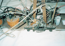 |
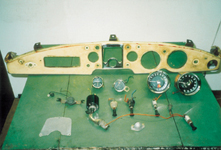
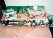
On Ratty I cut through the wiring loom with a hacksaw where it passed through the bulkhead and disconnected the heater controls before undoing the dashboard securing bolts. The whole assembly, complete with the wiring and controls still attached, was then placed on a shelf in the workshop until I was ready to begin its restoration. Prior to starting I took photographs from every angle, particularly from behind, to capture as much information as possible. The photographs shown with this article are only a small sample of the many taken and they have proved an invaluable aid as I reassembled the dashboard.
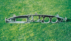
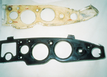
Now I had a good record of where everything was located and how it was connected I felt I could confidently strip the dash to its bare metal frame. I was careful to keep the original vinyl covering intact to use as a pattern for cutting the new material. I also cleaned and checked each instrument on the bench as it was removed. The speedometer and rev counter I connected to their original cables and function checked by driving the free end with an electric drill. It was pleasing to find that both instruments worked perfectly and displayed a steady indication of speed and rpm. I tested the temperature gauge by placing the sensor first in boiling water and then in cold water and I determined whether the fuel gauge functioned by connecting it with the sensor from the fuel tank and a temporary supply from a battery. As the float was raised and lowered the gauge displayed higher and lower fuel levels.
 |
|
 |
 |
It was at this stage that I noticed that there was an ammeter fitted to the dashboard even though this was not original equipment. I am unsure when it was fitted, but it is a high quality instrument supplied by Smith’s stamped like the rest of the gauges and switches with a manufacture date of March/April 1959. The first owner may have specified it from new but I suppose its origins will remain a mystery. It is my personal view that any car fitted with a dynamo should have an ammeter to ensure it is charging properly and I decided to keep it on the rebuilt dashboard. To check its function I made a simple circuit across a battery with a headlight bulb and observed the correct discharge of 5 amps.
As I removed each switch from the dash I cut the wires connected to it leaving a short length to act as a guide when reconnecting the wiring loom. Once again I checked the function of each switch by making a simple circuit with a headlight bulb across a battery. In this way I could be sure that everything worked under load and there would be no risk of malfunctions later. My cautious approach in this matter is due to my experiences with ancient electrics on other projects. Strange things can happen when the contacts of old switches become corroded with lack of use over many years! I was very pleased to prove that everything functioned as intended and nothing had to be replaced. Not bad considering the years of neglect.
 |
 |
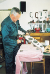 |
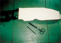
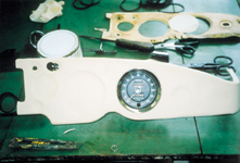
The dashboard metal frame was, apart from the addition of the ammeter, completely standard and had not been defaced with unwanted modifications. The next step therefore was to strip and paint it before recovering with new vinyl. A new painted surface was important to the overall finish of the vinyl because any surface imperfections on the metal would show very clearly once it was covered. As mentioned I used the original vinyl as a pattern for cutting out and found that it was essential to work on the new off-white material with surgical gloves to avoid marking the cloth. I used Dunlop impact adhesive S1358 to attach the new vinyl to the dash taking particular care to apply an even coating to both the metal and the back of the vinyl. As I stuck the vinyl to the dash each instrument and switch was fitted to ensure the covering was pulled into the pressed recesses. For some of the smaller recesses it was easier to use suitably sized formers and a ‘G’ clamp to stretch the vinyl into position before fitting the switch.
 |
 |
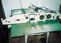 |
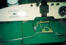
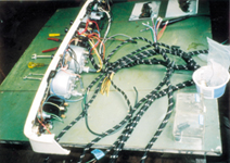
The lower edge of the dashboard is finished with a bright metal strip and this needed to be pop-riveted into position along with the chrome loudspeaker surround. Now I had to face the puzzle of the wiring. With the dash lying face downwards and the old loom to hand as a reference the new loom was gradually connected to all switches. This appears to be more difficult than it is because in no time all the wires were connected with no mysterious loose ends and it was possible to make a neat job of the wiring in this area. I am hopeful that all systems should function correctly once the battery is fitted.
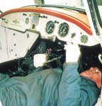
The last step was to fit the completed dash and the attached wiring loom into the car. I had to feed most of the loom through the large hole provided in the bulkhead but it was obviously designed to accommodate this amount of wire and all went well. It did mean I had to work in some peculiar positions to see what I was doing but without the seats fitted this was not a problem even for my inflexible aching back!
After I have connected the wiring loom to all the various systems the next job will be to rebuild the carburettors. This is another job I shall relish and will hopefully talk about in my next article.
 |
 |