A Twin Cam called Ratty – (Part 8)
As I may have already mentioned before, when I restore a car I try to complete the stage I am working on before tackling anything else. This then avoids the risk of being swamped by what seem like too many insurmountable problems at once. It is a simple strategy but it has served me well in other rebuilds over the years and it has been especially helpful with Ratty. So far I have completed the chassis, bodywork, spraying, rear axle, suspension and brakes, oblivious to the difficulties which may be lurking ahead. You may argue therefore that it would be folly to abandon this recipe for success, but I have broken my rule. I had started the engine rebuild when the new trim that had been on order suddenly became available.
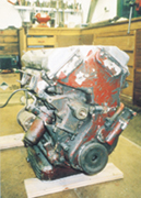
| Engine before restoration |
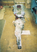 Engine and gearbox before restoration |
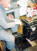 Dismantling the twin cam drive chain |
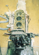 Cylinder head off, not too bad inside |
First of all let me tell you what progress I have made with the engine which had been stored in the workshop since being removed from the car over eighteen months ago. Until now I had resisted the temptation to make a full examination of the internals because I knew if it proved to be a disaster inside then it might stop me in my tracks and be the final straw in a difficult rebuild. I was however looking forward to the challenge of getting to know the twin cam engine design and building it up to be a reliable and powerful unit. The downside was that when the engine was removed from Ratty there were signs it had been severely abused. The engine mounts were bent and the starting dog had been smashed off, both signs that the car had hit something and the engine had lurched forward with considerable force. I was concerned that because the engine would not turn it could mean there was also considerable damage to the rotating parts.
In the end the engine proved to be no worse than others I have stripped and in some respects it was in remarkable condition, even the oil left in the sump was reasonably clean. The cylinder bores and crankshaft were standard size indicating that the engine had never been rebuilt. There were no burnt out valves or other problems in the cylinder head and no broken parts to contend with anywhere in the engine. My only difficulty concerned the piston in the rear bore which had seized solid and it needed significant persuasion before it could be removed. The ‘significant persuasion’ took the form of a sledgehammer which I used to strike a suitably shaped piece of hardwood, formed to the shape of the piston crown. By shaping the wood I was looking to spread the load and avoid cracking the light alloy piston and this technique was successful, if a little crude.
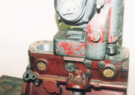 Reboring the cylinders |
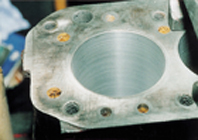 Detail of rebored cylinder liner. Note the bore has not been honed at this stage |
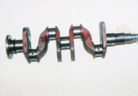 Reground crankshaft |
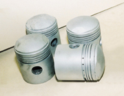 Original pistons before piston ring grooves are recut |
Unless you have access to a workshop with large machines it is necessary to contract a specialist to undertake cylinder reboring and crank regrinding. I know from experience that it is getting more and more difficult to find a really trustworthy engine machinist who is used to working on the older style of engine. The engineer I use is so busy he does not want me to pass on his details in ‘Enjoying MG’ because he would not be able to cope with any extra workload. I decided to think of an alias for this article and he suggested I refer to him as Dick Turpin the notorious highwayman because his workshop is near the Great North Road. Dick Turpin on his horse Black Bess was famous you may recall for robbing the rich at gunpoint. The Dick Turpin in this article is a much nicer man although people still end up giving him lots of money!
With the engine fully dismantled it was time once again to make my periodical acquaintance with ‘Dick’ and take him the engine block, crankshaft and pistons for assessment. There was the usual banter when we first met about being “far too busy” and “even if I take the job on it will cost a fortune,” but eventually he became serious and inspected the parts. I knew the pistons for the twin cam engine are peculiar to that model and would therefore not be easy to replace. Dick’s advice was to fit sleeves to the bores and then refit the original pistons. Even the piston rings were special and Dick decided that replacements could be adapted from Vauxhaul parts and fitted to modified ring grooves. The crankshaft and piston rods were crack tested and found to be sound and no significant wear was measured on the main bearings. Only the big-end journals needed grinding and these were reduced by 0.010 inches to remove some slight scoring.
The twin cam cylinder head is a beautiful piece of design compared with the push rod 1600cc ‘B’ series engine and is the reason why the twin cam engine is so powerful. When I removed all the valves and examined the design of the head I was surprised that I could see right through from the inlet port, across the combustion chamber and out the exhaust port. Not much to slow the flow of gases here but I felt there was still some room for improvement. The surface of the inlet and outlet ports for example was very rough and there was an intrusive bulge around the inlet valve guide. With a bit of patience it was possible to smooth all these surfaces and generally enlarge the cross sectional area of the inlet port by 15 percent. I hope that these alterations can be seen more clearly in the photographs. Bob West a twin cam specialist with a business near Pontefract in Yorkshire has suggested replacing the engine valves with a new design that he has tried and tested. He believes this should offer further improvement to gas flow. As soon as the valves are available I shall rebuild the cylinder head and with the reconditioned block back from Dick, the whole engine can then be reassembled.
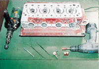 Polishing the ports on the cylinder head. Note that the two ports on the right are finished, the two on the left are still to be polished |
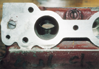 Detail view into the inlet port. Protusuin around the inlet guide is seen to restrict the flow. |
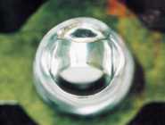 Same port as shown in photo 10 after reshaping and polishing |
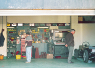 Bob West’s workshop |
As I mentioned earlier about the time I started the engine I heard from Bob West that Ratty’s new trim was finished. You may recall from my earlier reports that I had to scrap all the original interior which after thirty years of infestation by colonies of rats was in a disgusting state. Even the seat frames could not be saved because the originals had been replaced with bucket style competition seats. I had talked with a number of suppliers and heard very good reports about Bob West who was able to provide all new trim, including seats and frames. He was extremely busy when I first spoke with him so I decided to place my order for the trim at once to avoid holding up progress at a later stage. Now I knew the interior was ready I arranged to visit Bob to see his workshop and facilities and collect my order. I was not disappointed with what I found there, a first class organisation! Bob employs his own trim specialist Les who makes and fits all the MGA trim for the cars in the workshop where I spent a very enjoyable and instructive morning. Les willingly passed on many invaluable tips to help with trimming Ratty and his enthusiasm inspired me to start on my car’s interior.
One of the things that struck me when I got home and spread the trim out on the garage floor was how much there is to fit into such a small car. The colours I have chosen are as close as possible to the original production records for Ratty with dark red seats and side trim panels and grey carpet. The trim quality is very good and I am looking forward to fitting it all later in the rebuild. Les had stressed that installing the new headlining would be a challenge. He had explained that it was really important to make sure that the three curved supports were polished to allow the headlining material to slip easily into the ideal position during installation. Les would probably have made a better job than me but at least the installation went smoothly with this important piece of advice.
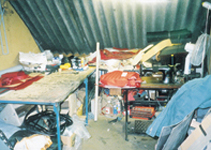 The trim shop with the seat covers next to the sewing machine |
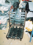 New seat frame for Ratty ready for upholstery |
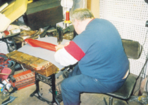 Les busy stitching the armrest to the prop shaft tunnel carpet |
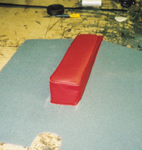 The finished armrest |
Once the headlining was in it was time to fit the front and rear windscreens, which are notoriously difficult tasks. Bob had supplied me with new windscreen rubbers and the first step in the installation was to put the glass in the rubber. Easy you might think?
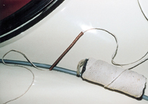
The new rubber was as stiff as plastic and the three-piece glass rear window would not stay in place long enough for me to offer the whole assembly up to the window aperture. It was time to sit down for a rethink! The solution I discovered was to tape the glass to the rubber as it was fitted to keep it in place until it could be offered up to the window frame edge. If I thought fitting the glass to the rubber was challenging I had not yet tried the next step, fitting the whole assembly into the window aperture. The approved technique described in the workshop manual is to place strong cord around the inside rubber lip with the aid of a short insertion tube. (See photograph.)
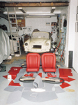 There is a lot of trim in an MGA coupe! |
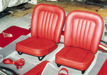 The De Luxe seats for the MGA are very comfortable |
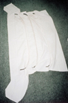 New headlining with the original metal supports fitted |
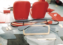 Note the new rubber or the three-piece rear windscreen |
As the installation proceeds the idea is to push the window from the outside whilst a second person gently pulls the cord on the inside of the car. What the workshop manual does not explain is just how physical and frustrating this job is and that the outer lip must also be pulled into position as you work round the window.
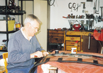
My long suffering wife Janet was the outside ‘pusher’ and I elected myself to be the inside cord ‘expert’. The window did eventually fit and we are still on good terms, facts that say more about Janet’s strength and good nature than my patience! Let’s just say that I would not willingly fit another MGA coupe rear window, at least until the memory of this attempt fades. After the physical effort of fitting the rear screen the front installation was almost easy by comparison and using the now practised technique it only took a short time to complete.
 |
 |
 |
| Patience is a virtue! Fitting the rear screen on a coupe is a challenge |
Cord and insertion tube used to fit the windscreens. The tube makes it easy to put the cord around the rubber lip |
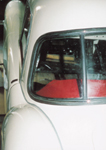
Rear windscreen fitted with the original chrome inserts |
I have not yet decided which tyres to buy and this is delaying a long overdue photo session on the drive outside. I hope to get the car mobile before the next update and to take some more general photographs. There is also a good chance that the engine will be finished and possibly installed by the next issue.