Bob’s Projects – The Nuts and Bolts of it!
The MGOC has a very large membership and the reasons people join the Club are many and various. Some for the social activities, others for the benefits such as insurance targeted to older cars and their owners and some for the travel opportunities, and some for the technical support. This article is not aimed at those who can afford to pay someone else to build and/or maintain their MG but at those who enjoy doing it themselves.
I was talking to Roger Parker the other day and we came to the conclusion that an article giving some basic facts about what holds our prized MGs together might be well received. I am of course talking about the many and various nuts and bolts we are likely to encounter when working on our cars classic or modern and the most suitable tools (Part II) to use when maintaining them.
So in this edition of Enjoying MG I present something different, giving me time to catch up on the work on the electrics of my ZB K4 Magnette project.
First – Bolts
We encounter various terms used to describe our nuts and bolts. The most common being:
- The head type
- The type of drive
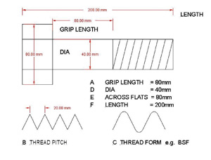
- The thread pitch, B
- The thread type – (form) C
- The diameter, D
- The distance across the flats of a nut or bolt head, E
- The length, F
- The grip length, A
- The material
- The tensile strength.
- The sheer strength
(Some of these terms are illustrated in Fig 1)
Note 1: A fastener threaded from head to tip, is not a bolt but a machine screw regardless of head type
Fig 1: Bolt details
Head types
Commonly found head types are: –
- Hex
- Hex Din
- Round head
- Cap head
- Button head
- Countersunk
- Cheese head
Note 2 : Whereas a normal 10mm Hex Bolt may measure 17mm across the flats, the Hex Din bolt will only measure 13, 14 or 15 mm.
Note 3: About head types: when using plain bolts i.e. not Din types, (or nuts for that matter) a plain washer should be used between the object being secured and the nut or bolt – particularly when an article is softer, the cylinder head for example. Din bolts and nuts obviate this need as they have a built in washer.
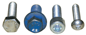
Fig 2: Bolt Heads Left – right:- Hex, Hex Din, Socket Cap, Button Cap
Drive types
All but the Hex headed bolts and machine screws may be found with a number of different methods of rotating them:
- Cross head
- Phillips
- Pozi-drive
- Star
- Allen
- Torx – Male and female
And a variety of security drives
Note 4: I know that many people tend to confuse Phillips and Pozi-drive screws and screwdrivers, referring to them all as “Phillips”. Original Equipment (OE) screws on an MGB are likely to be Phillips headed. On an MGF they will be Pozidrive. The difference lies in the shape of the cavity and thus the screwdriver tip.
Phillips bits and ‘drivers are marked PH 1, 2 or 3; Pozis – PZ 1, 2 or 3.
In Fig 3 below, the difference in shape of the Pozi and Phillips tips can be seen together with the fact that the Pozi has small flanges between the main drive flanges. Be careful as this is not always the case!
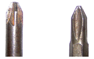
Fig 3: Phillips v Pozidrive Left – Pozi Right – Phillips
Thread types
A commonly found bolt on a B is a 5/16 UNF. UNF: – Unified Fine is the thread type, 5/16” is the diameter. As the distance across the flats of the hexagonal head is 1/2 inch. The bolt is commonly known as a 1/2 inch AF. It will very likely be marked on the head with an S. Supposedly High Tensile, but not very High Tensile.
In the beginning – for us anyway in this country the commonly used threads were BSW, BSF, BA and Cycle. (British Standard Whitworth, British Standard Fine and Cycle (used on Motor Cycles).
Whitworth Engineering have to my certain knowledge been in business since the 19th century, manufacturing gun barrels etc. The Whitworth thread form is generally regarded – now even in the USA as the finest of all forms. However (probably as fallout from WW2 lend lease agreements) we were invaded by American Standards – namely UNC and UNF. Unified Coarse and Unified Fine.
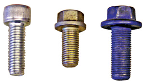
Fig 4 : Threads Left to right :- Metric 1.5, Metric Fine 1.25, Metric superfine 1.0 mm pitch
Finally in crept the Metric threads:- Metric standard, Metric Fine and Metric Superfine. Also found in this form are AN aircraft quality very high tensile bolts (ideal to secure brake calipers).
My Magnette (except for the bolts securing the rear brake adjusters, which are BSF) and the various MGBs, MGCs, and Midgets use UNF nuts and bolts and BA nuts and bolts on the carburettors. V8s also use UNF except where a bolt threads in to alloy when a coarser thread, UNC is needed.
Modern MGs, ZR, ZS, ZT and the MGF all use metric bolts.
Note: Modern bolts you will be pleased to know, are not created using dies, they are formed or rolled so that no material is lost. It is better when trying to repair a damaged thread to use a thread file rather than a die where more material will be lost.
Materials and Tensile strength
Most bolts (and nuts) you will come across will be made of steel. The Tensile strength of a bolt is basically the force needed, applied end to end, to pull it apart.
If any of our readers have done an engineering apprenticeship they may well, as did I, have made a tensile test specimen. The Sheer strength of a bolt is the force needed across the diameter of a bolt to cause it to break. You may have heard used, the terms “single” and “double sheer”. I shall illustrate them later.
I am sure many of us have replaced the nuts and bolts securing manifolds to down pipes or Cats to centre pipes with Stainless Steel (or as our German friends so aptly put it, Rostfrei) items. They don’t corrode so easily. Stainless Steel hardware, for our purpose comes in two grades, A2 and A4. By the way, Note 5: Do not use Stainless bolts and nuts to secure Discs and Calipers. Use aircraft quality or at least High Tensile items.
UNC and UNF bolts are marked on the head with a letter which identifies the Tensile strength. The average bolt will be marked with an “S”, higher tensile, a “T”, “AN” or “Aircraft Quality”in ascending order. Metric Bolts are marked with a number which is the grade and indicates the tensile strength. Fig 5 shows some examples.
Nuts
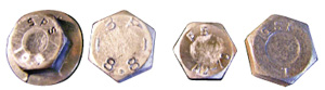
Fig 5: Head markings Left to right – 10.9 hex Din, 8.8 hex, A2 stainless. T grade hex unf. Below is a table which gives some typical metric Tensile and Sheer strengths
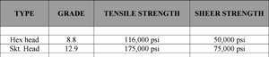
Fig 6: Table 1. Strengths
Below are shown some nuts.
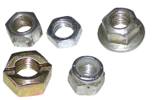
Fig 7: Nuts. From left to right: Hex nut, Hex half or T nut, Din nut, Binx lock nut and last the Nyloc
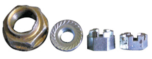
Fig 8: More Nuts. From left to right: used deformable hub nut, din serrated, castellated, castellated T nut
A word or two about these nuts: All of them are available in Metric, UNF and UNC threads. I shouldn’t need to say much about the standard hex nut. The T or half nut is used where space is at a premium. By the way all the lock nuts are available as T or half nuts and can be very useful at times. The Din Hex nut you will find on all the modern MGs. The Din serrated nut is a form of lock nut and is ideal for securing wiring lugs for grounding purposes. The Binx nut is an all metal lock nut which can be reused. The Nyloc nut should only be used once. The castellated nut is found on our older MGs where it is used, locked with a split pin to secure hubs, Kingpins and track rod ends. It is also found on modern MGs and Rovers in some places but I usually replace it with a Nyloc. The big nut is a deformable nut very often found on our modern MGs securing the hubs.
Note: Please never use split locking washers. Use a plain washer and a Nyloc or Binx nut.
A favourite fastener of mine is the Nutsert. The Nutsert is used when you need to secure something in a position, on a panel for example where you can’t get access to the other side. It is inserted through a hole rather like a blind rivet. When the tool is compressed, the shank of the Nutsert is deformed on the blind side of the panel so as to secure it. Fig 8A illustrates this and Fig 9 shows the tool with a 5mm Nutsert mounted on it.
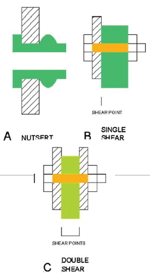
Fig 9: Nutsert and shear
General information:
Fig 8B above shows two items fastened together with a nut and bolt in “single shear”. The total load is taken at one shear point. Fig 8C shows an item secured in double shear. The load is split between two points on the bolt. Wherever possible try to do this.
Referring to Fig 10. When fastening two items together:
* Try and use a bolt with a grip length as shown. When the nut is tightened the sheer point will be on the shank of the bolt, not where the thread is. Whenever the shank changes section a “Stress Point” is created.
* Make sure that the amount of thread protruding from the nut is at least equal to half the bolt diameter.
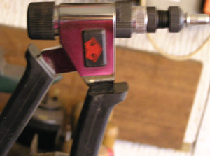
Fig 10: Nutsert and tool
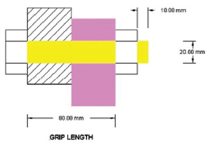
Fig 11: General Information
Bob Pulleyblank