MGB Crankcase Breather
Every engine needs to be able to breathe. Without this ability the engine will expel oil from any area it can, from its oil seals or by forcing oil past the piston rings. In turn this can lead to high oil consumption and a very messy driveway. To avoid this excessive crankcase compression, each engine has a built in breather system. On the A series and B series engines the breather system is split between the rocker cover cap and the crankcase breather. The replacement of the cap is a straightforward service item that should be carried out every 12,000 miles. However, crankcase breathers, as such, cannot be serviced and tend to be left alone on the engine. Indeed, the important role the breather plays is often overlooked especially when a reconditioned engine is fitted. Ignoring this vital component could lead to high oil consumption and even cause damage during the crucial running-in period.
All the crankcase breathers rely on a vacuum to scavenge the system. The early models of MGB relied on the vacuum from the inlet manifold. To avoid too much vacuum ‘pulling’ oil through from the crankcase a valve was installed, often referred to as the mushroom valve on top of the inlet manifold. As the engine revs rise the vacuum increases, as this happens the valve closes and therefore restricts the pull the breather system has on it. Too much vacuum would cause oil to be pulled through resulting in high oil consumption and clouds of oil smoke out of the exhaust, neither of which is desirable.
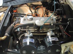
Early engine with ‘mushroom’ type vale on top of the inlet manifold |
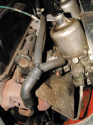 The later cars used the carburettors as a vacuum take off |
Many competition cars often have extra breathers fitted on their rocker box covers and sometimes even the bore of the breather pipes from the crankcase is increased. This is to allow for extra breathing to take place because for most of its working life the race car engine will operate in the higher rev range.
The later MGB engines took the vacuum from the carburettors. This decreased the effect of the increased engine speed ‘pull’ of the vacuum but not completely. To avoid pulling oil droplets through, an oil trap was placed inside the crankcase breather. It is this later type that we are looking at and we will be replacing the oil trap filter.
Removal
The first task is to remove the crankcase breather from the tappet chest side of the engine. The 1/2″ unf headed bolt used to secure the assembly to the side of the block can be reached and released without removing the carburettor or exhaust manifold. However, when you come to replace it, it’s much easier to install and seal correctly with these components removed. It’s therefore recommended that you remove the carburettors, inlet and exhaust manifolds before removing the breather. This is a relatively straightforward task involving the removal of the air filter, carburettors from inlet manifold, spacer blocks heat shield and finally the inlet and exhaust manifolds. Access will now be much easier.
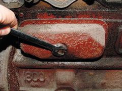 Removing the breather from the side of the engine block |
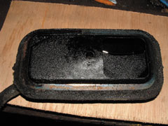 Dirty and partially blocked internal of the crankcase breather |
Once Off
Now that the breather is off the car you need to clean up the body of the assembly. This will make it easier to work with and prevents dirt and grit from becoming trapped inside the breather itself. Once clean, hold the breather firmly in a vice by the edge flange. Take an angle grinder with the thinnest cutting disc your local tool shop can supply and very carefully cut down three sides of the inside breather plate as shown in photograph 5. You should now be able to gently prise back the plate to reveal the gauze inside the breather. Try to bend this access tab as little as possible as you are aiming to return it in to the same position without any distortion. Now that the breather’s internals are revealed, it is time to prise out the wire gauze which will be thoroughly clogged with old oil.
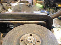 Carefully hold the breather in a vice and use a very thin cutting disc to open it up |
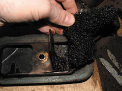 Bend the ‘tab’ back once cut to reveal the gauze of the breather |
You can now, by using either a degreasing agent or petrol, thoroughly clean the body of the breather. Pipe cleaners are very effective to ensure that the tube of the breather is completely clear. Once it is thoroughly clean you can put the body to one side. A choice must now be made with regards to the internal gauze. If it is very dirty and almost solid with old oil then it is unlikely to respond to cleaning. However if you think it will clean up sufficiently well, use some degreaser or petrol to clean it and then dry it off thoroughly. On the breather that we dismantled we found that the gauze could not be reused. As there is no standard replacement item available we employed a pan scourer. Many stores now sell a stainless steel type pan scourer which look rather like a lump of metal swarf but they are made of stainless steel and have the huge bonus of not breaking up and being ‘breathable’.
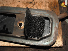 Remove and inspect the old breather gauze |
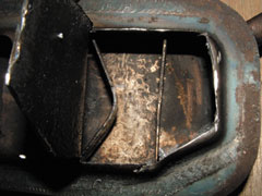 The inside need to be thoroughly cleaned out, including the pipe part. Note the metal strips to help retain the gauze in place |
Which ever route you take with the gauze you can now install it back in to the body of the breather. Make sure you tuck it in to the strips of metal that make up the securing cage – you do not want any part of the gauze breaking free in to the engine as this will result in a rebuild being required! With the gauze securely in position you can bend the tab of the breather body back in to place, and ensure a good flat finish.
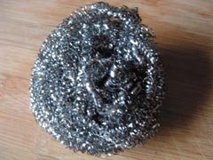 Stainless Steel Scourer used as a replacement gauze |
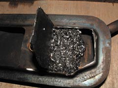 New gauze in place |
The next stage is to weld up the section that you cut into on the breather, so that it re-seals where you have cut though with the grinder. This is to make sure that the engine breathes through the gauze and you do not get a bypass situation that could lead to high oil use. A MIG welder is ideal for this as you can use small spots of weld, rather than a continuous run to avoid the heat damaging the breather. Once the access hole’s cut lines have been fully sealed you can then carefully grind the welds flat if required.
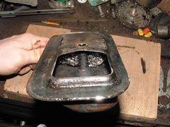 Position the gauze carefully |
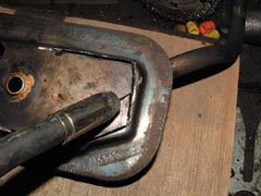 The tab has now been bent back into its original position and can be welded shut |
With the new gauze in place and the metal casing re-sealed you can give the exterior a coat of paint to complete the reconditioning of the assembly. Once the paint is dry you can, using a new gasket and lots of sealer, bolt the breather back on to the engine. Be very fussy about the positioning of the breather, as it can be a little tricky to line up and ensure an oil tight seal. However, with careful fitting and plenty of sealer you can do it. The other auxiliary components can now be bolted back on using new gaskets. Once everything is back in place the engine can be started and the breather checked for oil leaks.
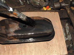 Repainting the breather |
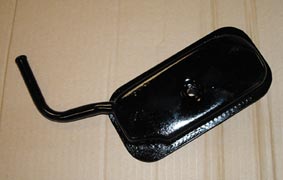 The whole assembly, once painted, can be bolted back on to the block using a new gasket and sealer |