MGF Head Gasket Failure Part 3
Oil should already have been drained leaving only the coolant to drain. If the pump is to be changed then this will see a rapid draining from the engine and system and a suitable washing up bowl (I suggest you do not use the one from the kitchen, and if you do I disclaim any responsibility for the domestic strife that will follow) or similar under the front of the engine will catch this. However, soaking the cambelt that is to be reused is a bad idea, so it is best to drain the coolant by getting under the car and detaching one of the hoses where it joins the underfloor metal pipes.
If there is oil contamination in the cooling system then this needs to be flushed through, which is a pain of a job as you never seem to be able to fully clean the system, with sediment later collecting in the header tank, but at least this can be removed and cleaned reasonably easily later and will eventually ensure that these residues are removed. Any coolant contamination within the engine will mostly drain out through the sump drain if left long enough as indicated earlier, and remaining residues will be small enough in volume to be mixed with fresh oil and the water content boiled out and purged by the breather in a short period of running.
However, if the internal contamination is heavy and of a thick consistency then don’t bother changing the oil filter yet and get some cheap 10/40 oil to use with a flushing agent, or go straight for flushing oil and use this to run the engine for a while to flush it through before changing to a new filter and good oil. This aspect is jumping ahead a bit as we have yet to sort the gasket problem so to this we must return…
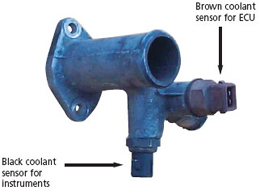
Coolant elbow from cylinder head showing sensor positions and functions, even though later sensors may be a different colour
Cam wheels need to be removed and here the problem is locking out the wheels whilst the (17mm head) bolts are loosened. A cam-locking tool is used here, although it is possible to use a suitable screwdriver or similar through the spokes of the non-VVC cam wheels and levering against one of the bolt heads holding the cam cover backplate to the head, the VVC needs a proper locking tool. The bolts can often be tight due to thread lock previously used, and in the case of VVC engines this is a good insurance policy to follow when refitting, as it is known that the bolts on VVC inlet cam wheels have come loose with catastrophic results! Thread lock on the bolt threads is advised!
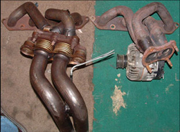
K series exhaust manifolds, pre 2001 on the right
The cam wheels need to be removed as the cam cover backplate is extended below the head gasket line and bolted to both the head and the block, which does rather make this aspect of the job more complex than it ideally should be. Yes it is possible to remove the lower fixing bolt, but the shape of the plastic cover means it will not come out unless the main engine-mounting bracket bolted to the block is removed. If you try to remove it then the cover will break, and if this is already found to be broken then this is a clear indicator that this is not the first time the head has been removed. If the cam cover backplate has been broken then this allows the head with cam wheels still attached to be removed as one. It is a shame that this is not a production route as it makes the job so much easier, compared with having to struggle in a restricted space. However, the standard arrangement doesn’t offer this simplified route and so normally the cam wheels have to be removed and this then allows the head can to be removed.
The exhaust downpipe has (or should have been) previously loosened/removed if the new Land Rover lower rail is to be used with the Land Rover multi layer head gasket. If not then now is the time to remove this. In every case of gasket renewal the exhaust manifold has to be disconnected from the head and here it is held on by five 15mm headed nuts and studs. It’s not uncommon for the end studs to come loose and be the source of exhaust blowing, and neither is it uncommon for the studs to come out with the nuts when you loosen them. Where studs come out as well it is best to separate the studs from the nuts (using a vice) and to clean both up so that the nuts will spin on to the studs very easily. This makes refitting so much easier.
Unfortunately accessing the five exhaust manifold fixings requires the exhaust heat shielding to be removed and this can come in two main different designs depending on the age and spec of the car. All variations are simple to remove although reaching the various bolts and having enough room to wind them out is another matter. In addition the two lower nuts are not easy to access compared to the top three, especially the one nearest the gearbox. Once all out though the manifold can be eased forwards off any studs remaining in position and gently allowed to drop down and rested. If there are any issues with the manifold to downpipe studs then this is the time to get these sorted as only the lambda (oxygen) sensor wiring needs unplugging and the plug unclipped and fed through to allow the manifold to be removed from the car.
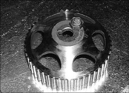
VVC broken cam bolt that results in a seriously broken engine. Almost always caused by not being tightened properly
Note also that an early factory/dealer fix for a rattling exhaust was to add a bracing bracket between the two studs nearest the engine on the manifold to downpipe flange to the engine block, so check this out because the manifold will of course not move if there is one of these brackets still in place.
Next job is to move to the inlet side, and through the aperture from the boot reach in and with appropriate sockets and extensions loosen the seven fixings holding the inlet manifold to the head. The combination of nuts/studs and bolts differs between the plastic and alloy manifolds but this doesn’t alter the removal sequence. Alloy manifolds though have a steady bar between the underside of the manifold and the block, and the manifold end bolt is removed and the block end loosened. When all are removed then the manifold can be drawn back and rested.
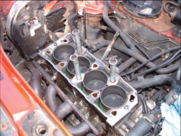
The importance of not turning the engine over when the head is removed can’t be overstressed. Here are home made liner retainers that use original bolts to secure them
The job is well advanced now and attention moves to the top of the engine. Pre 2001 1.8i engines have a distributor cap and normal pattern HT leads, VVC engines have four super long individual HT leads between the two double output coils and each plug. 2001 and newer engines have two double output coils sitting on top of the cam cover under an additional plastic cover with just a pair of short HT leads to the plugs.
For the pre 2001 engines remove the plastic cover with ‘Rover’ moulded into it to expose the HT leads on each plug. Remove each lead from its respective plug and whilst lead lengths are different for the 1.8i and easy to identify, the long individual leads of the VVC are easily mixed up and so mark each lead. Remember number one cylinder is closest to the front, cam cover end of the engine. Note two there should be two rubber blocks for neatly holding the leads that slot into two channels formed in the cam cover casting. Many cars have lost these over the years and whilst it is not a vital item to be missing many have puzzled looks when wondering where these blocks go during reassembly. Note also that disconnecting the leads from the plugs is sometimes very tight and so take care not to break the plastic tops of the leads if you have to resort to pliers or similar.
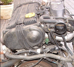
Early VVC engine with ultra long individual HT leads vanishing under the inlet manifold to the coils
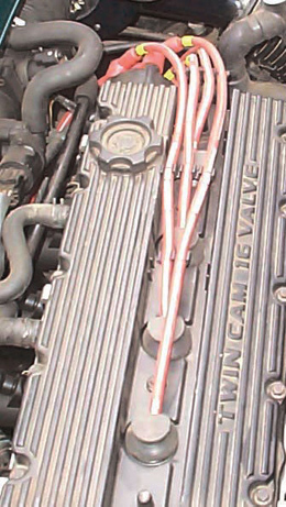
Pre 2001 MPi HT leads and distributor cap
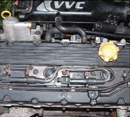
All 2001 on MEMS 3 engines use a pair of coils mounted on top of the engine. The same principle as earlier VVC engines, but much better
For the 1.8i remove the HT king lead that connects between the centre of the cap and the coil and hang it out of the way. Now remove the two screws/bolts holding the distributor cap to the head then remove the cap (plus oil/flash shield) and the connected plug leads and place in a safe place away from the working area. The rotor arm can be left in place.
There are two plugs and two wiring plugs to be disconnected from the same main coolant outlet from the head, exhaust side at the gearbox end. The hoses are different bores so can’t be mixed up, but the two electrical plugs can and so you make a note of which one comes from where, for correct refitting later.
The cam cover is then removed and yes there are an awful lot of bolts holding this in place. The cams and the heads of the ten through bolts are now visible and using the specific E12 socket for the bolt heads you loosen each bolt by a turn at a time in the reverse sequence for tightening essentially moving in to the centre from both ends. Prepare a piece of card with ten small holes and a marker at one end to signify the front of the engine and in turn remove each bolt, wipe with a rag and insert into the same relative position hole in the card to keep reference for each bolt to the position it comes from in the engine. If you are going to renew the standard air filter element then you can use this as a great bolt holder.
When all ten bolts are removed then gently rock the head from side to side (inlet towards exhaust and back again) to break any seal between head and liners without moving the liners. It becomes obvious when the seal has broken and the head is ready to lift. You do not just lift a head as you can easily lift a liner too and then that means further engine strip down and resealing the liner lower seating to block. The process is to almost roll the head off the block then lift.
You also want to create an secure area where the head is to be removed to and be aware that you will have a fair amount of oil released during this process so plan a route for both the lift out and over the car and where you going to place the head. When ready lift the head up and out of the car, it is an advantage to have an assistant helping at this point, and place the head on its side, NOT THE FACE, otherwise you could damage valves that are open.
Once the main through bolts are removed do not attempt to turn the engine over unless you have the specific liner retaining tools in place, or until the head is refitted and the bolts tightened, otherwise the liners will be disturbed.
Part Four next month
By Roger Parker