MGF Head Gasket Replacement Part 2
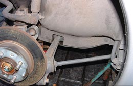
Now you need to raise the rear driver’s side of the car, remove the wheel and also the soft and soggy insulation style cover on the MGF (plastic on a TF) held in place by three fixings. The top one into the alloy engine mounting support will often be missing on older cars where the screw has corroded into the alloy and been broken off on a previous removal. If this is the case it‘s an extra five-minute job during refit to drill and add a new screw and flat washer. Removal of this cover provides access to the lower part of the engine and the front pulley.
The alternator belt is tensioned from the crank pulley and now there is a need to loosen this and release the belt. The usual means of doing this is to loosen the locking bolt on the adjuster bar to alternator, then loosen the bolt where this adjuster bar is bolted to the engine, and then a 10mm headed bolt is usually found hidden behind the alternator end of the adjuster bar, at 90 degrees to the two locking bolts, and this is how the adjustment is wound in and out. The main pivot bolt of the alternator will have to be loosened slightly and this is a 15mm nut at the front of the engine easily accessed from above. Once the belt is loose it can be slid off and hung up out of the way.
Rear right wheel removed showing weather cover and two plastic lower fixings. The upper self-tapping screw, which always seizes in the alloy is just out of shot
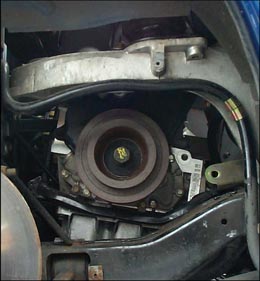
Cover removed to show access to the crank lower pulley. Note here the alternator bracket already disconnected to simplify belt removal
Note as the alternator is being moved there’s potential for shorting the main power feed so battery disconnection is advised. Front Wheel Drive (FWD) cars have an additional belt for power steering [PAS] and there is a spring loaded tensioner which has the tension removed by turning the 13mm hex in the casting and inserting a steel locking pin like an Allen key to hold it retracted. Cars with air con have a combined alternator and compressor drive belt that has a similar spring tensioned belt tensioner as the FWD PAS pump along with another hex headed lump on the casting to use a spanner to apply leverage and release tension for belt removal/refitting. Also note that with air con vehicles the alternator top bolt has to be removed and the alternator moved forward to allow access to the exhaust manifold to head bolts.
At this time those of you who do not have the benefit of an air compressor and a good quality air gun are advised to loosen the crank pulley bolt, not fully removed at this stage, only loosened. Before doing this, select a half inch drive socket of 22mm size with extension bars to a Tee bar with a good long handle. Look at the pulley wheel and locate the small timing notch on the edge nearest the engine. Then turn the pulley (and engine) to match the single moulded timing mark on the plastic cam belt cover, at just past the 12 and 1 o’clock position, not any of the several additional timing marks in approximately the 9 to 10 o’clock position.
Now you need to crack the pulley bolt loose and the tee bar will usually need to be extended with a suitable tube, so that the considerable torque often needed to crack the seal is achieved – or use air tools. Locking the engine is usually necessary when using hand tools, therefore place the car in 4th gear and have an assistant stand on the brake pedal whilst you use the big lever to crack the pulley nut loose. When the bolt cracks do not loosen any further as you need the pulley to remain correctly seated for a while! As the loosening process usually turns the engine back a few degrees you want to re-align the pulley timing marks and the cam wheel timing marks described in the next paragraph. The easy way to turn the engine over here is to leave the car in gear and use a lever between wheel studs and turn until the marks are back in alignment, then take the car out of gear.
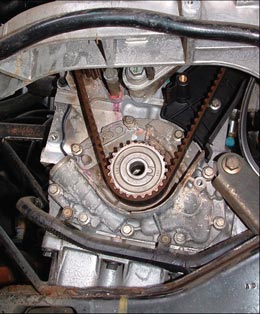
Front pulley removed; note two dimples on the face of the remaining belt pulley at the 12 o-clock position. These line up with the cast in line on the oil pump body behind, which with the angle of this shot is in line with the right dimple
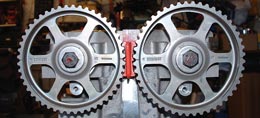
Showing the correctly aligned cam wheels with a cam locking tool fitted to prevent either wheel turning
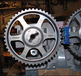
MPi cam wheel has marking for inlet and exhaust cam fitting. You use the marking and position appropriate to what cam is fitted
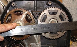
Showing the way a straight edge is used to prove correct alignment. The head in this case is a VVC but the same applies to all engines
Next remove the top cam belt cover (remove the five 8mm headed bolts and loosen the bottom 10mm headed bolt, just left of the engine mounting which is also a water pump fixing). The belt comes off by easing forwards, and with a little jiggling, lift upwards. When removed the front cam wheels are exposed and here you can double check the timing marks are aligned noting that non VVC engines have two timing marks per wheel only one of which is applicable.
These two sets of timing marks per wheel often cause confusion. There are also two alternative fitting slots for the cam location dowel, to add further complication. Both of these two slots have an identifying mark, one with ‘In’ and the other ‘Ex’. This is interpreted to the cam the wheel is fitted, so if it is fitted to an inlet cam then you use the slot marked ‘In’ and vice versa for the exhaust.
In addition to these slots in the centre of the wheel there are two different timing notches on the outer edges of the wheel. On the ‘spoke’ next to each mark is stamped ‘inlet’ or ‘exhaust’ and once again the cam that the wheel is fitted to dictates which is the valid mark to use. So here if the wheel is fitted to the Inlet cam then the timing position used is the notch marker ‘Inlet’. The picture (top centre) should make this explanation clearer and you may wish to highlight the relevant marks with chalk, Tippex or a wax pencil.
Returning to the issue of setting the correct timing marks for correct positioning of crank and cams, needs both relevant notches directly next to each other so that if a straight edge joined the centre of each cam locating bolts, the line would dissect both timing notches. The crank pulley notch should be in line with the previously described alignment, but if not then it would be 180 degrees out and need a single turn of the crank via the lever and wheel studs as previously described.
The cambelt can now be removed and loosening the tensioner located below the inlet cam on the head does this. Two types of tensioner exist, the manual one used on all engines to late 1998 and all VVC engines, and the autotensioner that arrived late 1998 for all non VVC engines. They have different bolting arrangements with the manual one using an Allen headed bolt for main securing and a small 8mm headed additional locking bolt on the bracket. The auto tensioner has a double 10mm normal hex headed bolt fixing. When loosened retract the tensioner in the minimum set position and just nip up the bolt that is outside the tensioner wheel to hold it in that position for ease of belt removal and later refit.
Now I move back to the lower part of the engine and remove the crank pulley bolt, and the pulley. This pulley and the cambelt inner pulley may be stuck together, but they are separate parts and the outer pulley should come away separately. A few sharp taps with a light hammer in the centre often breaks any seal that has formed here. With the main pulley removed you can access three 8mm headed bolts that hold the lower cambelt cover in place and remove this. This exposes the lower part of the belt and allows full examination of it and importantly examination of the water pump.
The K series water pump change was covered a few issues ago but here the general guidance is always to check for signs of coolant leaks and staining from dried coolant. Obvious leaks need no further explanation, but problems of a minor nature are less easy to make a decision on. The picture, previous page top left, shows an engine of just 33,000 miles and five years of age and clearly there is a small degree of staining emanating from under the toothed wheel. This can only come from one place and this is past the main shaft seal and this is something that never gets better, only worse. I have also seen instances where the pumps toothed wheel becomes very clearly worn. Where there is ANY sign of leaking or damage then the advice is to renew. Some regard the time of a cambelt change to be the time of a routine water pump and tensioner replacement, and I have to say this is quite a sensible approach.
Incorporated into the head gasket change the added cost is very small and even done professionally will essentially only add the cost of the pump (and tensioner). The same approach applies when doing a routine belt change as 95% of the work is already done and the pump change is a simple 10-minute additional element.
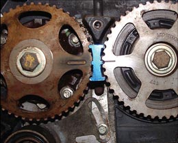
The same VVC engine showing the simpler marks on that engine’s pulleys
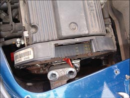
Engine mounting bolts removed with jack and wooden block under engine to support. This allows the engine to be dropped enough to remove old cambelt and fit a new one if this is being replaced
The cambelt is now carefully slid off with no metal or other sharp tools that could damage it, and even if it is to be renewed you have to avoid cam wheel damage. (I always renew the belt if there is any damage or oil contamination, or the belt is past the half way mark to the next routine change. I also closely examine the tensioner for any signs of wear or bearing noise when the head is removed and renew at the slightest hint of problem.) If the belt is to be reused then you can simply lay it as far out of the way as possible. If removed then chalk an arrow to show the direction of rotation and ensure it is refitted as it came off.
If the belt is to be replaced then there will be a need to disconnect the right hand engine mounting, simply removed by removing the two 18mm headed bolts visible from above the engine, next to the cam cover, after supporting the engine from underneath with a jack and suitable piece of soft wood between jack saddle and sump. Lower the engine slightly to make a gap between the two parts of the engine mounting and feed the old belt out, and reverse when refitting the belt. I am familiar with taking care not to contaminate or damage a belt that is laid loose whilst I work around it, but ideally there may be an advantage in removing the belt and placing to one side. Only leave the engine mounting disconnected for the time needed to remove or refit a belt, otherwise refit and tighten the two bolts.
To be continued next month.
by Roger Parker