MGF Head Gasket Replacement Part 4
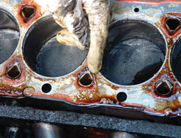
Now is the time to examine various parts and make a decision on what depth of rectification work is needed. The first part to look at is the gasket and check for damaged or displaced silicone track. Generally this will be found on the exhaust side, which runs hottest, and shows as sections that have become unstuck from the stainless steel part of the gasket (see image below).
Next the head face is examined and you are looking for any signs of the gasket fire rings having sunk into the face and created a groove. This will be most obvious again on the exhaust side, and only a very light marking is acceptable. Deeper grooves mean the head face material has become softened and without specific engineering work the head will not be re-usable. If this is present then take the head for a professional examination. Do be aware that typical of most twin cam head designs there will be a lot of engine oil trapped around the cams and so when turning upside down there will be a big mess!!! Take the opportunity to drain this oil from the head over a period of time as it will greatly assist achieving a clean rebuild.
The other aspect of the head face to look at is whether there is any distortion and that involves placing a known good straight edge across the head face in a number of different directions and seeing if there is any obvious distortion. Once again if there is then take the head for professional examination. Both conditions have solutions to recover this head but the depth of damage will dictate if this is actually viable.
Finally there is the potential of corrosion where low concentration of antifreeze, or infrequent changing, has allowed corrosion to occur where coolant is in contact with the alloy. If this undercuts the gasket at any point then the surface has to be machined. Normally only around 8 thousands of an inch is permitted to be removed from the head face, but the reality is that many still work well with more than double that removed. The least removed the better, is always the motto to follow.
Many garages automatically skim all heads, which is not always a sensible move because of that small official skimming limit of just 8 thousands of an inch (0.2mm) and remember skimming not only reduces the head face thickness, but also its rigidity and susceptibility to further distortion later on. If the face is already flat and unmarked then why do something that is not needed? On older engines there is a further thought on whether the head has been previously skimmed and so any further skimming may be inappropriate. The distance between the head face and the face onto which the cam carrier sits should be 119mm plus or minus 0.1mm, so accurate measuring will confirm any previous skimming. I have seen heads skimmed 15 thou and some more, but without adding support of a stainless steel shim I would not like to say how long the engine will be reliable for.
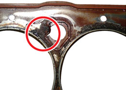
Along with the common gasket failure point is sometimes aggravated by corrosion as shown here
Not that we end the story here as many skims can actually create other problems, as most engineering shops, not looking to create a specific surface finish, will be using a very sharp tool to cut the head face. This actually makes the surface more prone to porosity and can lead to other problems so a ‘blunt’ tool skim usuallyprovides a more suitable finish. Mind, if the Land Rover gasket or the Payen ‘Head Saver shim’ is being used then both use a stainless steel shim that is bonded to the head face so this acts as a sealing face.
I will also mention one aspect of the liners that can cause problems and whilst not so easy for the DIY person with little familiarity with the K series to get to grips with, it may highlight a potential problem area and save a lot of work that would otherwise be wasted. It relates to the fitted height of the liners in terms of the gap between the top of the block and how much higher the top of the liner sits. The age and spec of the engine will determine the degree of protrusion of the liner but nominally it should be between 3 and 4 thousands of an inch. Place a straight edge over the top of the liners and check all liners are level, and then you can gauge how far the liners sit above the block face using feeler guages.
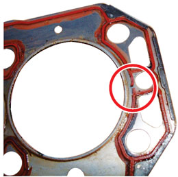
A less common failure of the gasket
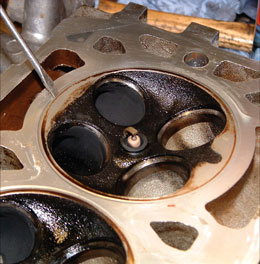
Close up of damage head face with indentation shown by screwdriver, this is measured in the other image…
Interestingly I believe that the engines made between 1996 and 1999 used 6 to 8 thou gap for the liner to be proud, and if so then it is interesting to see that these engines are the ones with the highest incident of gasket failures (hmmm, another possible ingredient to the overall K series recipe). Probably the best pointer to be used here has to be to use that straight edge again and see that all liners sit at the same height as any liner that has sunk points to a problem within the block and something that has to be addressed otherwise all the work building the engine back up will result in a recurring major problem.
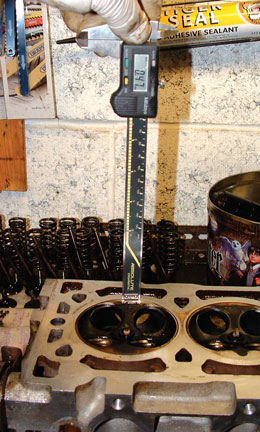
Here the indentation of a softened head is measured at a significant 0.47mm!!
Now if the head and liner checks are all passed then there is yet another important check and this is with the through bolts. These are very specially engineered stretch bolts and only have to be renewed if they fail this test. Take each bolt in turn and place it in the hole it came out from. DO NOT DROP THE BOLT in, as this will damage the thread in the lower rail. HAND tighten the bolt without using any tools until you find the bolt stops turning. This is where any stretch in the bolt thread has occurred and you now measure between the block face and the underside of the bolt head. If the measurement is more than 97mm renew the bolt, if it is less than this then the bolt is serviceable and can be reused with no worries. I do actually operate with an additional 1mm clearance and replace when that measurement exceeds 95mm, but that is a personal preference not the official one. Likewise many prefer to renew the bolts as a matter of course and this is fine too, as long as the possible £70+ extra cost is acceptable. Be wary of eBay offers on new replacement bolts as non original spec bolts may not have the correct stretch characteristics.
At this stage assuming that the head and bolts are suitable and ready for reuse we have a need to carefully clean all these parts, especially gasket faces and this includes the exhaust manifold and the alloy inlet for those cars with that type of inlet. The plastic inlet manifold has a seal, not a gasket, and it is a flexible moulded ‘rubber’ item that sits in a moulded groove in the manifold. These have been known to give problems and should be renewed as a matter of course.
The exhaust manifold nuts often come out with the studs and I suggested earlier to separate them in the vice and to clean the threads so that the nuts are free and easy. Note that VVC and MPi have different stud and bolt fixing arrangements. The same applies to the stud into head threads and before the head goes back on it is the time to refit the studs fully into the head (using a pair of nuts tightened together on the stud to get it fully in if needed). The benefits of free running nuts will become clear when you come to refit the exhaust manifold.
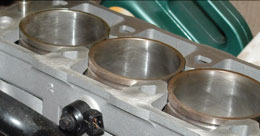
Liners standing proud, just visible in this new engine
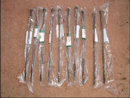
Main through bolts, here from Land Rover, as they were cheaper than MG Rover sources
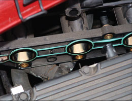
When the HGF is an internal failure the contamination gets everywhere!
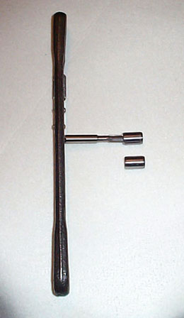
Steel dowels here having an 8mm tap run down them for future proofing – see text
A small but very significant change to the engine specifications was introduced during early 2001 when the original nylon dowels used to locate the head to the block were changed for steel ones and since that time all new gasket sets always include a pair of new steel dowels. This one small change has a disproportionately large impact on helping to reduce head gasket failure by reducing the amount of movement that can occur between the head and block. I also run an 8mm tap down the inside of these dowels before fitting as it will assist in future damage free removal when the steel and alloy react and corrode together over a several year long period. Dowels have been supplied with a chamfer on the ends, but sometimes a slight additional chamfer on those ends that will be engaging with the head is also helpful with initial location of the head into the correct place. Some also find that a small flat filed on the outside that allows trapped air to escape that sometimes makes it difficult to settle the head onto the dowel; such is the close interference fit of these steel dowels.
The dowels are gently tapped into the block, until the tapping sound turns ‘solid’, and then the head gasket is laid over the dowels with the side showing ‘TOP’ facing up, not that anyone should be able to fit it the other way as it is would clearly sit wrong! If the Land Rover gasket and lower rail is being used then it is time to drop the sump and remove the two retaining bolts holding the original lower rail to the block, and fit the Land Rover replacement rail (see October 2006 EMG).
With the Land Rover head gasket there is an additional and separate thin shim and one side has a bonding agent that has to be fitted towards the head face, as this becomes activated by engine heat, and it bonds to the head face.
The head can now be replaced onto the block and again the help of an assistant will make the job so much easier and reduce the risk of slipping and damage. The problem here is that you have to locate the head onto the locating dowels and accuracy is vital as rubbing the head back and forth until it drops into place is just not on, as the steel dowel will damage the head face. I find that if you have a good light source onto the block face you can ‘aim’ the head by looking down through the through bolt holes. Once in place put a drop of fresh engine oil on each thread and place the bolt in the correct hole and start the thread by hand, remembering you MUST NOT drop the bolts in as this will crush the thread in the alloy rail and lead to other problems.
Once all bolts are in place and you have the bolts started by hand, wind them all in until they tighten before using a torque wrench to tighten to the initial torque setting of 15lbs ft. Follow the correct tightening sequence even at this low level stage, before then starting with the first bolt again, and turning it a full 180 degrees. Go through the same tightening sequence for all ten bolts before retuning to the first bolt and repeating the process with a further 180 degree turn.
During the refitting of the head I always keep spark plugs fitted as there is nothing worse than having open spark plug holes and a bolt or similar accidentally dropping through into the engine. I did have this many years ago and was fortunate to be able to recover the lost bolt with a small powerful magnet on a stick. Once bitten twice shy applies, as knocking a plug gap out is firstly unlikely and secondly, of no consequence, so it makes sense to shut the door to a more serious problem. Incidentally, after an engine problem such as this I fit new plugs when all is back together anyway.
We are now over the summit and can see the valley below, but there remain a couple of ravines to cross before we get there…
Part Five next month