Midget 1500 Head Gasket Change
Picture a warm sunny summer’s day, a 1500 Midget, its hood down on a country road with an attractive blonde lady owner at the wheel knowing why she loves her MG. Then suddenly disaster, as the car expires in a cloud of steam and grinds to a halt at the road side. Almost immediately a passing AA patrol stops and strangely within a short period there are two other AA vans present! A potential head gasket failure is diagnosed and arrangements made to tow the vehicle to home. Great service and a good advert to become a member, especially when said lady is not a member. Now I wonder what influences applied there?
After the car was recovered, came the repairs and most important finding the cause of the breakdown. Indeed the fact that when the cooling system was refilled the engine would run – poorly – and specifically weak on number 2 and number 3 cylinders. Also detected was an external water leak that was traced up to the right side of the engine. Further examination showed poor compressions on those two cylinders and also water ingress.
The external water leak was investigated first before the head was removed as this was most likely to be the cause of the failure. Initially the loss of a core plug had been suspected. However, very close examination with a torch and mirror managed to pinpoint the leak coming from the metal water pipe that is fitted into the back of the water pump, and which runs behind the exhaust manifold to feed water through the inlet manifold and heater.
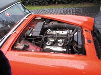
Remove bonnet for essential access |
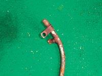 Corroded metal water pipe |
Removal of this steel pipe can be quite problematic at the back of the water pump housing due to long-term corrosion, but fortunately in this instance it did loosen – just. There is an additional anchor point on the end manifold stud and once this and the hoses were removed, the pipe could be lifted out. Very close examination revealed that corrosion had created a pin hole from which a stream of water would jet onto the engine block and give the indication that the leak was from the block. This corrosion is perhaps understandable for a steel pipe that has carried water over the last 25 years, but I suggest that many other 1500 Midgets could well have this little time bomb ticking away on a final countdown. An added complication is that there is not really a simple check that can be done for this problem because the corrosion occurs from the inside. So if your 1500 Midget suffers any loss of coolant here is the first place to look.
The lady needed her car back on the road so there was a need for a reasonably fast turn round and with a gasket set immediately to hand and assuming that the head was not warped or cracked then that left just the need to solve the water pipe failure. An added problem arose from the way in which the original steel pipe has a bolt on union into the rear of the water pump housing. Here a solution came in the form of standard 15mm household copper water pipe and bends. The inside diameter of the copper pipe being very close to the outside diameter of the steel pipe, allowed the original steel pipe to be cut a short distance from the water pump end and then the resulting stub carefully cleaned up. Internal examination of this stub is now possible and it was seen to be largely free from deep corrosion.
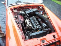 Inlet manifold pulled forward to reveal water pipe |
 New home made copper water pipe in place beneath manifold |
Once the outer surface of the stub was cleaned back to bare metal the copper pipe could be slid over and then soldered into place, leaving just enough free movement for the bolt union. The length of this pipe was adjusted so that a 90 degree bend was fitted then an additional short length of pipe before a tee piece and other short stubs to provide the required take-offs. Additionally where hoses were to be fitted a run of solder was added to the ends to provide a better purchase for them. This solution was quick, effective and cheap, allowing plenty of time to look into obtaining a genuine replacement part, although some time later the ‘Heath Robinson’ repair remains in place and is working well!
Replacing the head gasket was quite simple and followed the basic rules set out in the workshop manual. One point to make is that removal of the bonnet makes engine access comfortably possible, otherwise you operate with the motoring equivalent of keyhole surgery. Before removal draw around the location points where the hinges bolt to the bonnet so that it is a simple matter to replace the bonnet exactly where it came off.
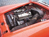
When the engine was turned over on the starter water spurted
out via the spark plug holes in cylinders two and three
First disconnect the battery for safety, then drain the cooling system, although here most of it had gone anyway. Next follow the list of procedures as shown in the workshop manual, which is a requirement whenever attempting this sort of job. The actual tasks listed are quite simple and sound straightforward so there is little point repeating them here. However, a simple instruction to remove so and so does not always turn out to be that ‘simple’ and here a few words can be of assistance.
Carburettor removal can be a fiddle especially when trying to access the two lower mounting nuts. It is often better to loosen the nuts evenly, top and bottom, this allows the carburettor to be progressively drawn away from the manifold and also gives a little more room for the nuts to turn, otherwise they can bind on the carburettor body. Also make a detailed note of the position of the throttle cable, linkage and return springs for ease of replacement. Sometimes a digital image pays dividends where the re-assembly is to be at some time in the future rather than later on the same day. The same applies to the main manifold to head fixings and spacers.
A classic simple ‘remove’ instruction applies to the temperature transmitter for the temperature gauge. In this car this was less important as the temp gauge wasn’t working, hence the lack of warning before the boil up, but problems often occur. The usual situation is when the inner temperature transmitter corrodes to the outer locking collar. When you come to undo the collar the whole assembly turns, winds up the metal tube from the transmitter until it is either squeezed shut or breaks. In either case it renders the gauge useless and rectification of this type of gauge is most definitely beyond the realms of DIY as a special process and material is needed when they are made or rebuilt.
The Manual says the exhaust manifold has to be separated from the exhaust down pipe. This may not be required as the manifolds can be separated from the head depending on the detail of the actual car. Some allow enough movement to achieve this (with a little persuasion though) but others don’t.
When removing the rocker shaft be aware that sometimes the pushrods have become stuck to their rocker through the oil film. This can also apply to the other end of the pushrod and so ensure that the tappets (cam followers) do not lift out when removing the rocker shaft. Likewise when removing the pushrods, a gentle turning motion as you lift is usually enough to break and seal and allow just the pushrod to lift. It is also a good idea to cut a flap from a cardboard box and make 8 holes in a line with a screwdriver. Mark one end with an F for front and then as the pushrods are removed insert each one through the holes to correspond with their position in the engine. Doing this not only keeps them in the correct order, but also ensures that they go back in the same way up. Whilst it should not make a difference, each pushrod beds to the surface of the tappet and rocker it works with, so any mismatch can accelerate wear thereafter.
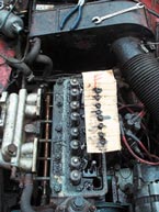
Keeping pushrods in order of removal
At this point head nut removal follows, which is far easier, and safer, when, a suitable lever is used. Loosening and removal in any specific sequence is not specified, but a habit of following one which is a reverse of the tightening sequence is not a bad thing. Remove the nuts and washers and another suggestion is to keep them in an order that enables you to replace them on the stub they came from. Whilst this is not a specified procedure, there is an advantage in knowing that the threads will usually wind on smoother so any torque setting is transmitted to holding the head on the block and not used to overcome resistance between nut and stud threads.
Once free, heads usually need little effort to break the seal between them and block, with gentle rocking being normally all that is required. Sometimes a little more force can be necessary, but do not use wedges between the head and block as surface damage is likely and this will lead to sealing problems when refitted. Sometimes the head can lifted by turning over the engine with the starter motor and using cylinder pressure to break the seal. Once the head is loose then simply lift it up and off the car, a job that is much easier with an assistant. Note that there will be much oil dripping from the head so prepare by laying some protective material over the car over where you intend to lift it and on the surface where you intend to place it. There will be a need to turn the head over so plenty of absorbent cloths or paper will be needed.
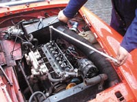
Keeping pushrods in order of removal
Now you can have a close look at the head gasket, which will probably have to be peeled off the head or block face. Detailed examination usually allows you to find the point of failure, but sometimes this needs an expert eye. If the cause of failure is not clear then seek assistance to identify what it might have been. Blind replacement of the gasket while the problem remains is futile, a point that becomes immediately apparent when the engine is restarted and failure re-occurs, needing another strip down. In this case the gasket failure is clearly seen between cylinders 2 and 3 with the composite gasket material having been ‘cooked’ and now breaking up.
Whilst the head is off it is prudent to examine valves and seat condition and look for any other obvious damage. One specific check is to see that the head face is straight and true by using a straight edge. This is an actual tool made with a very accurate straight edge and infinitely straighter than the average plastic ruler and similar edges that people use. In this case there was no light visible between the straight edge as it was placed against various parts of the head face. Although far less susceptible to damage, a check on the cylinder block is also worthwhile and in this case provided the same results.
Another consideration, particularly in these circumstances is the possibility of any other useful work being done whilst the head is removed. The main one is a conversion to run with unleaded petrol, if it has not already been done having this work carried out now means that a future specific head removal will not be needed, saving both time and money. It does mean that the repair costs will now be higher with any additional work, but if you planned to do it sometime, then this means that you have only one fitting cost.
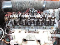
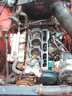 Cylinder head removed |
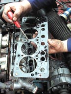 Examine the head gasket carefully |
If the head were to need additional work then looking to have unleaded machining or simply exchanging for an already converted head, or perhaps a head with additional power enhancing changes can provide a number of benefits. The range of options is quite wide, and the point here is to look beyond the problem and try and turn it from a negative situation to a positive opportunity.
Refitting follows a reversal of the removal sequence, but beforehand ensure all mating surfaces are spotlessly clean. Obviously, this means the faces of the head and block but also remember the face between the front of the head and the thermostat housing. Also, clean up all bolts because some, like those on the thermostat to head fitting will probably have encrusted shafts. When refitting the head pay attention to ensure that the new gasket is placed the right way up, and ensure that there is a new gasket between the head and thermostat housing. Finally, a drop of engine oil on the cleaned up threads helps ensure smooth accurate tightening.
The head needs to be torqued down correctly and here there is a specific sequence starting from the innermost nuts moving progressively outwards. It is also recommended to tighten progressively, so take a leaf here out of the modern day engines where several stages are involved. The actual torque of the head nuts is variously quoted at 46 or 50lbf ft, which seems to stem from some misprinting in the original British Leyland Manuals. Essentially 50lbf ft is not an excessive figure and can be regarded as appropriate for all engines. To reach this level it is suggested that a start torque of 25lbf ft is used then 40lbf ft and finally up to 50lbf ft.
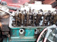
Aligning puhrods
Refit the pushrods and slide the rocker shaft into place. It is an advantage to pivot the rockers back to engage the pushrod with the ball of the rocker. Engaging this early makes for an easier fit of the rocker shaft and helps reduce the irritating tendency for pushrods to jam in the wrong place requiring the shaft to be re-lifted, disengaging other rockers from pushrods. Manually turn the engine over a couple of times to ensure that valve gear is settled then reset the valve clearances, which WILL need doing. Refit the manifolds and carburettors but at this stage leave the air filters off to allow initial tuning adjustments to be made.
Once the few remaining items have been refitted always replace the oil and filter as some contamination will inevitably have entered the sump. Then unless items like plugs and points are fresh it is a good policy to renew these as well to give the engine the best possible conditions to start and run correctly. Initially starting may be a little rough until the engine has ‘cleared its throat’ and normal working temperature been reached. During this period you will get smoke and an oily smell from dirty handprints on the exhaust manifold (just in case you think the car is about to burst into flames). Keep an eye on the fuel pipes, coolant hoses and generally look under the car for any signs of fluid leaks. When refitting used hoses it is not unusual to see small weeping from them requiring the clamp to be loosened, then hose gently turned back and forth to re-seat it before re-tightening for water-tight seal.
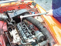
Torque wrench to fasten the head studs
Once the engine has settled down with any minor adjustments made to smooth out the running and you have confirmed that no fluid leaks exist, it is time to refit bonnet and go on a test-drive. On the test drive expect a trace of smoke from the exhaust, which often requires some more miles before settling down. On return, park away from where the work was done, and preferably over a dry area, let the engine idle for a few minutes before switching off so that any new leaks and drips will leave a clear tell tale sign on the road surface. Allow the engine sufficient time to cool before rechecking fluid levels and topping up as needed. All in all, the car should then be ready to be enjoyed again.