A Twin Cam called Ratty – (Part 15)
After three years Ratty’s restoration is nearly complete and this will probably be the penultimate article in the series. Following on from last month where I described the installation of the carpets and the interior, this month’s report covers the final work to complete the trim. I have also tested the electrical circuits and started the engine. In my final article I hope to be able to report a successful trip to get an MOT certificate, my first driving experiences and produce an analysis of the cost of the project.
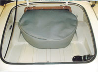
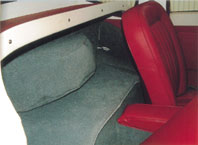
On Ratty the spare wheel is mounted in the boot but has a part protruding through the rear bulkhead, presumably to give more space for luggage. This means of course that some of the tyre is in the cockpit behind the seats. The original interior included a matching carpet cover to protect the passengers from any dirt on the tyre and a plastic cover in the boot area. My trim kit from Bob West included everything needed to complete this part of the interior to its original design. On later MGA models MG positioned the wheel behind the bulkhead to give more space behind the seats but at the expense of the boot space. I had no particular difficulty with fitting this part of the trim just ensuring that the carpet looked neat and tidy with the wheel in place.
Spare Wheel with cover in boot |
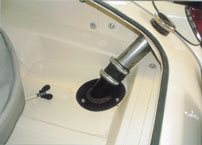
 Detail of fuel filler pipe |
My last job to complete the boot area was the installation of the petrol tank filler pipe. The pipe passes through the boot space on its way to the tank and it is vitally important to ensure that the rubber hose connector makes a fuel tight fit if fumes are to be avoided in the car. I also put new rubber seals around the pipe where it passes through the bodywork and the boot floor to avoid water leaking into the car.
Achieving a proper seal around the doors is an important finishing touch in any restoration ensuring that the driver and passenger are insulated from draughts, noise and water leaks. On an MGA this represents quite a challenge because the original seal was a combined ‘Furflex’ and sealing rubber which is now very difficult to obtain. The seal was made in a variety of colours to match the various interior colour schemes and on Ratty the car would have been supplied with red Furflex. Unlike later types of door seals where a soft rubber tube was placed between the closed door and the body, the MGA had a seal around the outside edge. This original seal design supported the door from up and down movement when the car was subjected to bumps from the road.
 Spare Wheel intrudes into cockpit |
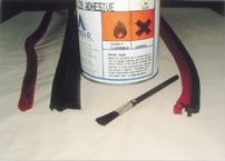 Two types of door seals |
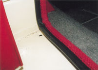 Incorrect door seal |
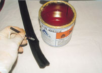 Preparing rubber seal for sticking |
I tried a number of sources to obtain the correct type of seal but failed to find anything close to the original ‘all-in-one’ design. In desperation I tried the seal where the rubber is between the door and body but as predicted by the experts it made the door difficult to shut. I then spoke to Peter Wood who recommended that I used a two-part system where the seal is stuck to the bodywork lip and then the Furflex is fitted over the top. He was able to supply me with the parts needed although the Furflex was light grey instead of red. I changed the colour with proprietary fabric dye and followed Peter’s instructions about fitting both the rubber and then the Furflex cover to each door. The results were spectacularly successful. Not only did the doors shut with a more satisfying thud but it was also obvious that they were now supported from the effects of vertical vibration.
I had noticed on other MGAs that an attractive stainless steel trim covered the lower part of the door seal between the sill and the carpet. This was part of the original trim and was fitted to protect the seal from becoming scuffed by the occupants’ feet as they entered and left the car. These were missing on Ratty and I was finding it very difficult to find replacements until I placed a message on the Twin Cam Group website. Jonathan Stein in the USA responded and supplied me with a very nice pair of trims as seen in the photographs. (What did we do before we had access to the Internet?) My sincere thanks to Jonathan for supplying the trims and putting one of the last pieces of the jigsaw in place.
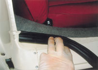 Attaching rubber seal to door lip |
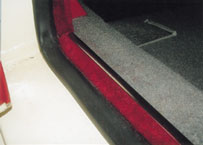 Correct door seal with stainless seal protector |
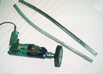
I encountered a slight problem when fitting the exhaust system because for some reason the pipe from the front section was the same diameter as the middle section pipe. It was obviously impossible to connect these two pieces of pipe but I suppose this was to be expected as I bought the front section second-hand at an auto jumble, the middle section new from a supplier and the rear silencer was a gift from someone else! I puzzled over this for a while before coming up with the solution shown in the photographs. I had some stainless tube of a smaller diameter than the exhaust pipe from which I fabricated a two-part coupling. These two pieces were reshaped to the same diameter as that of the exhaust pipe and the edges of the larger section were ‘joggled’ to form a seal. With two heavy-duty pipe clamps the joint assembly was placed over the two parts of the exhaust pipe like a muff coupling which made a very strong joint and an effective seal.
It was now time to think about starting the car for the first time. One of the tips I have picked up over the years is to wait until the end of a restoration before putting fluids into all the various systems. I then stand the car on top of a large sheet of clean paper or cardboard which ensures that leaks are identified as soon as they occur. It also helps if you have a distinctive coloured oil in the gearbox because it makes it more obvious where leaks originate once the engine and gearbox are filled.
 Stainless door trims found in USA (Note one as received and one polished) |
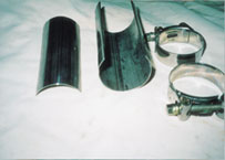 Exhaust Pipe clamp and connector |
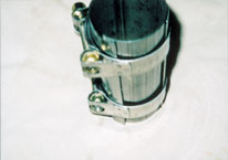 |
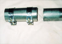 |
| Homemade exhaust pipe connector | |
My first action was to fill the cooling system with soft water collected from a dehumidifier mixed with a cup of machine cutting oil. This type of oil mixed with water is normally used to provide lubrication and rust protection to steel parts during machining. When it is added to a newly restored cooling system it imparts the same properties to the cooling water and protects the inside surfaces of the engine as well as lubricating the water pump. It also turns the water white and makes it easier to identify the source of a leak.
The first leak I found was in fact from the cooling system and originated in the water pump. This did not surprise me as I had rebuilt the original pump and had been unable to check it after making the necessary repairs. The water pump is reasonably accessible and once it was removed and dismantled I quickly found the problem. During the pump rebuild I had to reclaim the impellor by making a new bronze face as part of the sealing system. Unfortunately this new part was inadequately sealed to the impellor and water was leaking at this point. It was a simple matter to refit the new bronze part with sealant making the pump watertight.
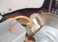 Bleeding the front brakes |
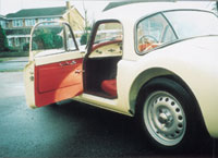 Let’s go for a spin! |
Putting oil in the engine did not cause any leaks at this stage but there was a small tell tale drip of oil on the cardboard right underneath the gearbox. I noticed what appeared to be a leak from the gearbox plug but I knew this was unlikely to be the source because it was sealed with plumbers Teflon seal tape. The actual leak was from higher up on the side of the gearbox where there is an alloy access plate attached with six or seven screws. I have experienced leaks here before on other MGs and is usually caused by oil running along the screw thread and out via the split in the spring lock washer. My solution was to replace the spring washer with a fibre washer and the leak ceased.
The next job on my checklist was to fill the hydraulic brakes with fluid and I chose to use Dot 5 silicon fluid instead of the more standard Dot 4 specification. The reason for this is that unlike the standard oil the silicon fluid is not hygroscopic and long term does a better job in protecting the brake pistons from corrosion. This is a very important point on a Twin Cam MGA because parts for the brake system are virtually unobtainable and have to be protected at all costs. In this case it made sense to use silicon fluid, especially as the car will not be used for racing and the brakes are unlikely to be tested to their full capacity. I would not recommend however anyone change the type of brake fluid in their car without the help of experts because of the safety implications involved.
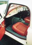 The Coupe has a very comfortable cockpit. |
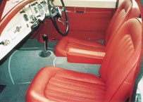 Everything in place at last. |
Over the years I have tried a number of different methods to bleed hydraulic systems and find the simplest is still the best. My favourite method shown in the photographs uses a short length of rubber hose with a tight fitting plug about 2 cm long in one end. The tube also has a short lengthways slit to allow air and brake fluid to escape. The tube is attached to the bleed nipple furthest away from the master cylinder and the nipple screwed open one or two turns. With a suitable container arranged to catch the fluid the brake pedal is stroked in and out a few times. The slit in the tube acts as a valve to ensure air escapes during each stroke and closes automatically as the pedal returns to prevent further ingress. With this method the bleed process is a single-handed operation and each nipple can be treated in the same way to purge the whole circuit. It is necessary to check and top up the reservoir after about three full stokes of the pedal. I found a number of slight leaks around the new brake pipe connections and once again the cardboard underneath the car was an ideal way to spot these as they occurred. There are around 23 pipe joints in the brake circuit and it is vital for safety that they are all completely sealed. Eventually all the joints were sealed and the brake pedal pressure found to be reassuringly firm.
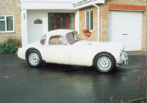 |
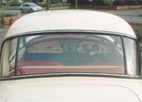 |
| Dodging the showers for the first outdoor pictures | |
As I placed the batteries in the trays under the shelf behind the seats it began to dawn on me that the car was nearly finished and I would soon run out of excuses to try the engine for the first time. I connected the positive earth and battery link cables and then briefly touched the cable clamp to the negative post. If by chance there had been a short in the circuit this would have caused a momentary flash, but all was well and I was able to make the final connection. I was pleased to find that all the systems responded except the fuel gauge which did not register the petrol I had put in the tank. This was quickly rectified, the level sensing float had stuck down in the tank and I was able to release it without emptying the fuel out. I switched on the ignition for the first time in thirty years and listened to the reassuring sound of the SU pump ticking as it pushed the fuel up to the carburettors.
I pulled out the choke and holding my breath activated the starter. Imagine my delight when Ratty fired instantly and with a roar burst into life, exaggerated by the enclosed confines of the garage. I had not warned Janet, working in the office above the garage, and this unexpected outburst brought her running down to see what had happened. She was delighted to witness this special moment as Ratty proved she was ‘alive and running’ at last! This first short run revealed the need for a few tuning adjustments and I noticed there was a complete lack of charge from the dynamo. The adjustments to the tuning were easy but the lack of charge caused a bit more head scratching.
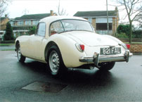 Coupe lines are elegant and simple |
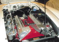 The engine bay three years on |
I checked for obvious faults such as loose connections and then worked through the dynamo and regulator standard fault finding procedures without success. Long-term followers of the Ratty story will recall the car has an ammeter fitted and it was here I found the reason for lack of charging. An ammeter was not included in the original MGA instrumentation and was therefore not provided for in the new wiring loom. I made my own conversion to include the ammeter in the circuit and made the mistake of connecting it through the A1 rather than the A terminal of the regulator. This had the effect of inhibiting the voltage regulator from connecting the dynamo to the battery but after rectifying this small error I was pleased to see that the dynamo worked as intended.
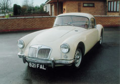 Out of the garage at last |
After three long years it is good to have a car that now at least starts and runs but at the time of writing has not been on the road. I have no illusions about what might be in store as I begin the process of taking Ratty for trial runs and of course the MOT test. As I said at the beginning the next report will cover this last step in the journey to put another Twin Cam Coupe back on the road but do I really want to see a final reckoning of the cost?
Richard Ladds